Rockwell Automation Publication 1794-UM066C-EN-E - April 2023 13
Chapter 2 Install Your FLEX I/O Adapter
3. Disconnect any user power wiring connections to the adapter.
4. Open the module latching mechanism and remove the module from the base unit to which
the adapter is attached.
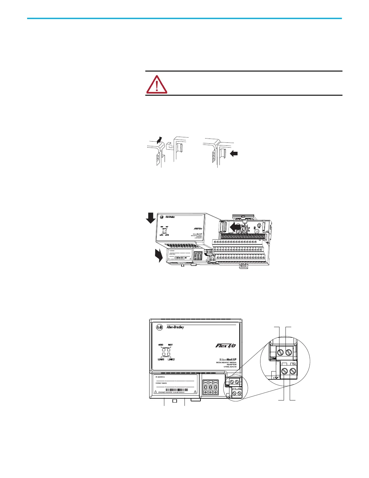
5. Push the Flexbus connector toward the right side of the terminal base to unplug the
backplane connection.
6. Release the locking tab and remove the adapter.
Before installing the new adapter, notice the notch on the right rear of the adapter. This
notch accepts the hook on the terminal base unit. The notch is open at the bottom. The hook
and adjacent connection point keep the terminal base and the adapter tight together,
reducing the possibility of a break in communication over the backplane.
7. Complete the adapter mounting as shown.
Push down and in simultaneously to lock the adapter to the DIN rail.
If the adapter does not lock in place, use a screwdriver or similar device to move the locking
tab down while pressing the adapter flush onto the DIN rail, and release the locking tab to
lock the adapter in place. If necessary, push up on the locking tab to lock.
When the adapter is locked onto the DIN rail, gently push the Flexbus connector into the
adapter to complete the backplane.
8. Reinstall the module in the adjacent terminal base unit.
Connect Wiring
ATTENTION: Verify that the Flexbus connector is completely clear of the
adapter. The slide must be completely to the right and the raised spot on
the slide visible.
 Loading...