14 Rockwell Automation Publication 1794-UM066C-EN-E - April 2023
Chapter 2 Install Your FLEX I/O Adapter
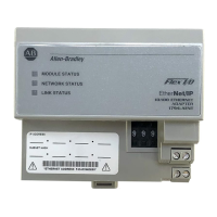
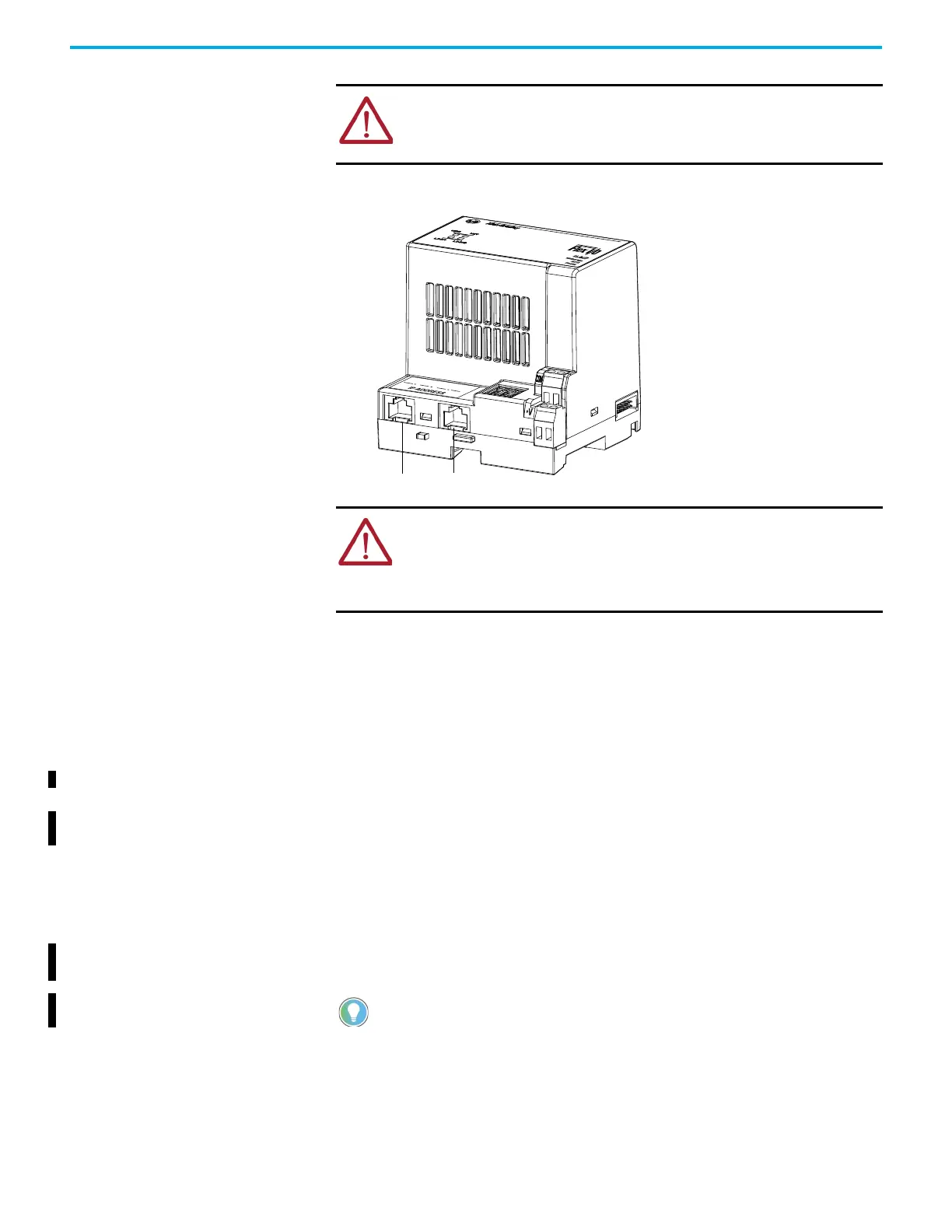
1. Connect an Ethernet network cable to the RJ45 connector (A).
2. Connect the redundant Ethernet network cable to the RJ45 connector (B).
3. Connect 24V DC common to the left side of the upper connector, terminal F.
4. Connect +24V DC input power to the left side of the lower connector, terminal C.
5. Use connections D and E to pass +24V DC common (E) and 24V DC power (D) to the next
module in the series (if necessary).
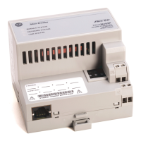
Set the Network Address
The adapter ships DHCP-enabled and with the thumbwheel switches set to 999. You can set the
network Internet Protocol (IP) address in these ways:
• Use the pen-push thumbwheel switches on the adapter. Press either the + or the - button
with a pen tip to change the number.
• Use a Dynamic Host Configuration Protocol (DHCP) server, such as Rockwell Automation®
DHCP.
• Retrieve the IP address (if previously set) from nonvolatile memory.
The adapter reads the thumbwheel switches first to determine if the switches are set to a valid
number. You set the node address by using the three-position pen-push thumbwheel switch using
a pen tip.
When the switches are set to a valid number, the adapter IP address is 192.168.1.xxx (where xxx
represents the number set on the switches). The adapter subnet mask is 255.255.255.0. The
adapter gateway address is set differently depending on the firmware revision:
• For Firmware Revision 1.013 and earlier, when the address switches are set to 001...254, the
adapter gateway address is set to 0.0.0.0.
WARNING: If you connect or disconnect wiring while the field-side power is on, an
electric arc can occur. This could cause an explosion in hazardous location
installations. Be sure that power is removed or the area is nonhazardous before
proceeding.
ATTENTION: When connecting wiring, torque terminal screws C, D, E, and F to 0.8
Nm (7 lb-in.).
If multiple power sources are used, do not exceed the specified isolation voltage.
Power wiring must be less than 10 m (32.8 ft.) in length.
Do not wire more than two conductors on any single terminal.
Press a pen tip into the center and perpendicular to the + or the - button to change the
number. You only need a small amount of force to press the button (approximately 2 N).
 Loading...