Rockwell Automation Publication MOTION-AT007A-EN-P - May 2020 13
DC-bus Wiring Guidelines Chapter 1
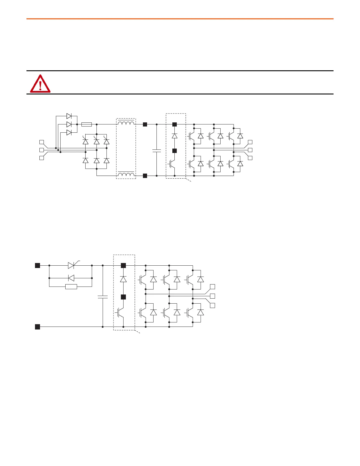
PowerFlex 750-Series (Frame 5 and 6) AC Drives
When ordered as an AC input drive, DC terminals are not provided on Frame 6 drives. During precharge, the SCRs of the front-end rectifier
are open and the bus capacitors are charged through the diodes and resistors from the AC input. After the DC-bus has reached precharge
level, the SCRs (when turned on) bypass the diode resistor configuration.
Figure 7 - AC and DC Input Schematic for PowerFlex 750-Series (Frame 5 and 6) AC Drives
PowerFlex 750-Series (Frame 5 and 6) DC Input Common-bus Drives
The precharge has a resistor in series with the positive DC-bus, ahead of the bus capacitors. An SCR is connected in parallel and when gated
on, it bypasses the resistor.
Figure 8 - DC Input Schematic for PowerFlex 750-Series (Frame 5 and 6) DC Input Drives
ATTENTION: PowerFlex 750-Series (Frames 5 and 6) AC input drives have no method for you to control the precharge sequence. To
avoid severe drive and/or equipment damage due to uncontrolled precharge, do not connect these drives to an energized DC-bus.
Optional for PowerFlex Frame 6 Drives
Voltage Rating
Catalog Codes 1 and A
Optional for PowerFlex Frame 6 Drives
Input Type Catalog Number
Position 5, Code 4

 Loading...


