Rockwell Automation Publication MOTION-AT007A-EN-P - May 2020 75
Kinetix 5700 Accessory Modules Appendix B
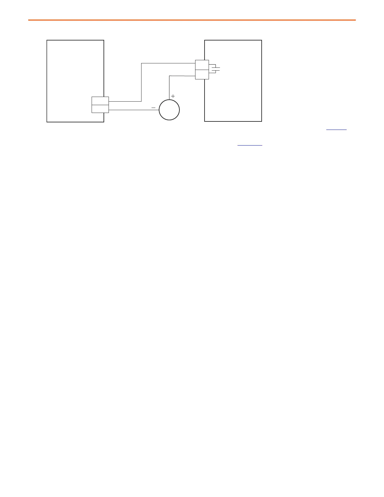
Figure 43 - Regenerative Bus Supply with DC-bus Conditioner Module
(1) Configure any one of four digital inputs as Bus Conditioner OK. For regenerative bus supply configurable functions, see Kinetix 5700 Servo Drives User Manual, publication 2198-UM002.
Refer to the Kinetix 5700 DC-bus Conditioner Module Installation Instructions, publication 2198-IN016, for additional installation information.
Extension Module
The extension module, when paired with a capacitor module, is used to extend the DC-bus voltage to another inverter cluster in systems with
≥104 A current and up to 208 A.
Observe the following extension module guidelines:
• The extension module is always mounted next to a capacitor module or DC-bus conditioner module and always positioned on the
outside of the system cluster (either first or last).
• Flexible bus-bars are included with the 2198-CAPMOD-DCBUS-IO extension module. So, if you have a 2198-CAPMOD-DCBUS-IO extension
module with a capacitor module or a DC-bus conditioner module, you do not need to order the 2198-KITCON-CAPMOD2240 or 2198-
KITCON-DCBUSCOND connector set separately.
2198-RPxxx
Regenerative Bus Supply
2198-DCBUSCOND-RP312
DC-bus Conditioner Module
Module Status (MS)
Connector
Digital Input
(IOD) Connector

 Loading...


