8 Rockwell Automation Publication MOTION-AT007A-EN-P - May 2020
Chapter 1 DC-bus Wiring Guidelines
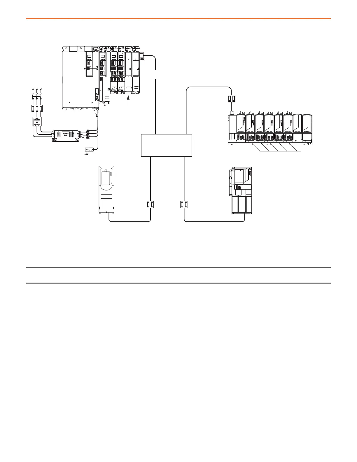
Figure 1 - Extended DC-bus Installation Example
DC-bus Connections
DC-bus cables and bus bars are used to connect drives in common-bus configurations.
DC-bus Cable
When using cables to connect drives to the system bus, observe the following guidelines:
• Use only unshielded cable for DC-bus voltage.
• Use 1000V rated insulation cable in this application.
• Make the DC+ and DC– cable distance as short as possible to help reduce cable inductance.
• Twisting the DC-bus cable together is not required, however, it is recommended to make sure the DC cables are routed close to each
other.
• The maximum DC-bus cable length (power supply cluster to extended cluster) is 70 m (230 ft).
• No single external DC-bus connection from the power supply cluster can exceed 70 m (230 ft). You can extend the DC-bus from the
right and left of the power supply cluster, but the total DC-bus length (including DC-bus cabling and DC bus-bar) from the power supply
cluster to all extended clusters cannot exceed 140 m (459 ft).
• The Bus Voltage Reference Source is configurable. When it is set to Automatic, the converter optimizes the Bus Voltage Reference for
the best converter setting. When it is set to Manual, you configure the desired Bus Voltage Set Point value for the Bus Voltage
Reference signal.
• To prevent nuisance bus-overvoltage faults, the maximum Bus Voltage Set Point of the regenerative bus supply reduces linearly from
750V DC to 715V DC as the DC-bus cable length per cluster increases from 0 to 70 m (230 ft) respectively.
IMPORTANT The interconnection of drives to the DC-bus, and the inductance levels between the drives, must be kept to a minimum for
optimum system operation.
MOD
NET
MOD
NET
MOD
NET
2
1
2
1
2
1
UFB
UFB-A UFB-B
UFB-A UFB-B
D+
D-
D+
D-
D+
D-
MF-A MF-B MF-A MF-B
D+
D-
MBRK
+
-
MOD
NET
D+
D-
MF
MODULE
STATUS
1
I/O-A
6
510
1
I/O-B
6
510
1
I/O
6
5
10
1
I/O-A
6
510
1
I/O-B
6
510
MOD
NET
2
1
1
I/O
6
5
10
OK+
OK–
EN–
EN+
MOD
DC BUS
Single-axis
Inverter
Dual-axis
Inverters
Bulletin 1321
Line Reactor
AC Line Filter
Circuit
Protection
Magnetic (M1)
Contactor
Line
Disconnect
Device
DC-bus Circuit
Protection
DC-bus Circuit
Protection
2094-BMxx-S
Axis Modules (5)
PowerFlex
750-Series AC Drive
2094-BMxx-Mxx-S
IAM Module
Common Bus Follower
2094-PRSx
Power Rail
DC-bus
Extension
Bonded Cabinet
Ground Bus
Kinetix 7000
Servo Drive
Bulletin 1492 Power Distribution
Terminal Block
Kinetix 6000 Servo Drive System
Kinetix 5700
Servo Drive System
Regenerative
Bus Supply
2198-CAPMOD-2240
Capacitor Module
2198-DCBUSCOND-RP312
DC-bus Conditioner Module
2099-BMxx-S
Servo Drive
DC-bus Circuit
Protection
Accessory
Modules

 Loading...


