Rockwell Automation Publication MOTION-AT007A-EN-P - May 2020 43
Regenerative Bus Supply Configurations Chapter 4
Contactor Enable Relay
The contactor-enable circuitry includes a relay-driven contact within the 2198-RPxxx DC-bus power supply. The relay protects the
Kinetix 5700 drive system in the event of overloads or other fault conditions.
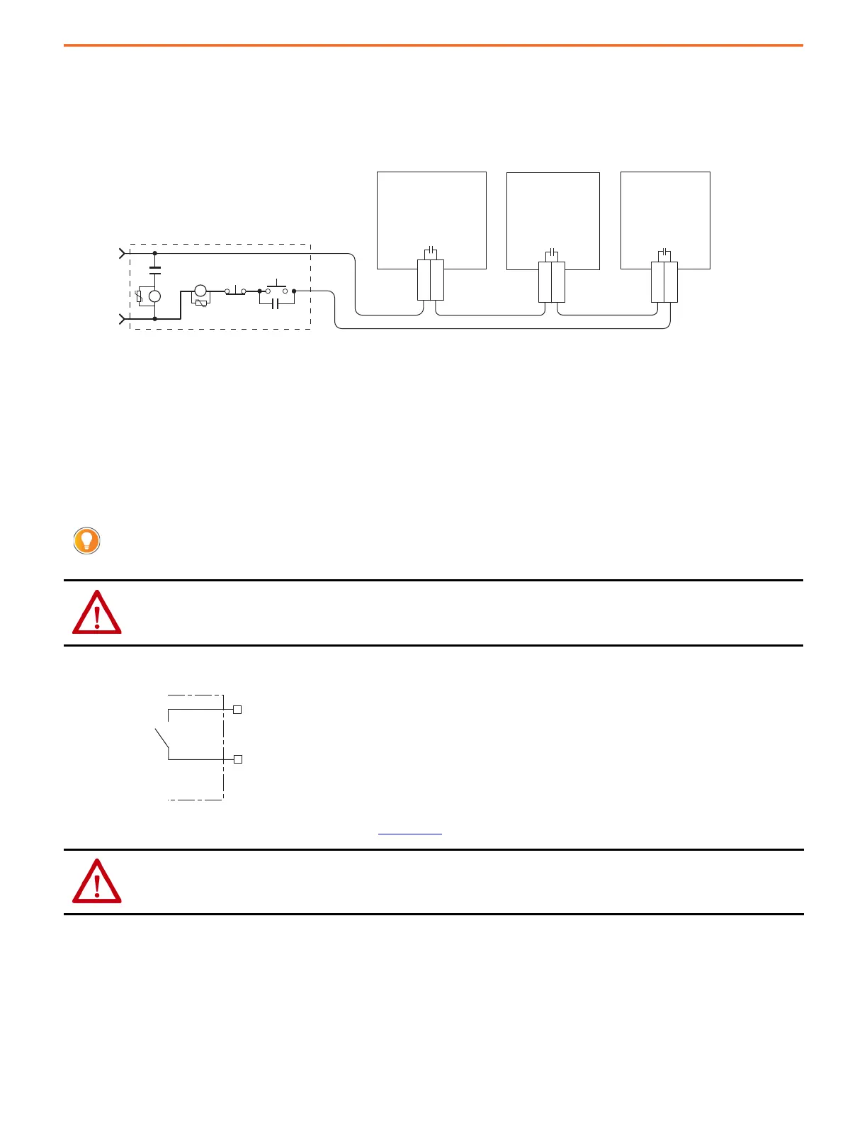
Figure 26 - Contactor-enable Control String
An AC three-phase mains contactor must be wired in series between the branch circuit protection and the power supply. In addition, the AC
three-phase contactor control string must be wired in series with the contactor-enable relay at the contactor-enable terminals.
PowerFlex 750-Series drives are not required to include a contactor-enable control string and they do not have a dedicated contactor enable
relay. Although not required, if leveraging Integrated Motion with a PowerFlex 755 drive, we recommend that you configure a digital output
from the drive as Contactor Enable and include it in the contactor enable control string.
A Contactor Enable output can be configured in the PowerFlex 755 drive in integrated motion only. The operation of this output is tied to fault
processing in the drive. The drive de-energizes the Contactor Enable output when an exception causes the axis to go to the Shutdown state.
Figure 27 - Contactor-enable Relay Circuit
Refer to Kinetix 5700 Servo Drives User Manual, publication 2198-UM002, for additional information on the contactor-enable circuitry.
This configuration is only valid when an auxiliary power supply is used for control power with frames 1…7 drives.
ATTENTION: Wiring the contactor enable relay is required for Kinetix 5700, Kinetix 6x00, and Kinetix 7000 drive systems to help
prevent personal injury or damage to Kinetix drive modules. Wire the contactor enable relay into your control string so that:
• three-phase power is removed and the power supply or regenerative bus supply is protected under various fault conditions
• three-phase power is never applied to the Kinetix 5700 drive system before control power is applied.
ATTENTION: For Kinetix 6000 (400V-class) and Kinetix 6200/6500 drive in common-bus configurations, the contactor enable
connections for leader and follower drives must be wired in series to the control string.
A contactor or other device that routinely disconnects and reapplies the AC line to the bus supply can cause drive hardware damage. If
an input device is used, operation must not exceed two cycles per minute (maximum) or damage can occur to the precharge circuit.
Kinetix 5700
2198-RPxxx
Regenerative Bus Supply
CONT EN+
CONT EN–
GPR2+
GPR2–
Kinetix 6x00
2094-BCxx-Mxx-S
Integrated Axis Module
Kinetix 7000
2099-BMxx-S
Servo Drive
CONT EN+
CONT EN–
STOP *
START *
CR1 *
CR1 *
CR1 *
M1 *
24V AC/DC
50/60 Hz
* Indicates User Supplied Component
Normally
Open
Relay
Power Supply

 Loading...


