Rockwell Automation Publication MOTION-AT007A-EN-P - May 2020 15
DC-bus Wiring Guidelines Chapter 1
Kinetix 6000 and Kinetix 6200/6500 Multi-axis Servo Drives
The Kinetix 6000 (400V-class) and Kinetix 6200/6500 drives are packaged, highly configurable, common bus products with one converter
module (IAM) and multiple inverter modules (AM) mounted on a shared backplane. Precharge hardware, which consists of a resistor in series
with a DC link inductor and the positive rail of the DC-bus, is mounted in the converter module. In all recommended common bus
configurations, the converter is not used; therefore, any non-Kinetix 6000 common-bus leader module that does not provide precharge is
required to add an additional external precharge circuit before connecting to any Kinetix 6000 common-bus follower IAM module.
An internal shunt resister (braking chopper) is included with each inverter module. To be used in a common bus system with Kinetix 5700
drives, the Kinetix 6000 system must be set to common-bus follower mode with the internal shunt modules disabled.
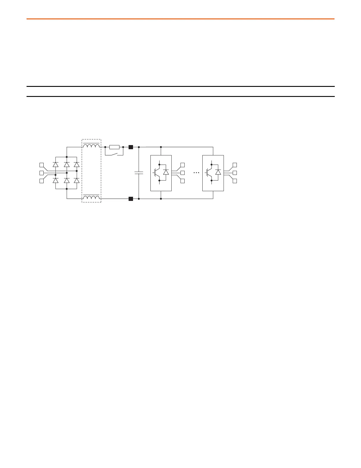
Figure 11 - AC and DC Input Schematic for Kinetix 6000 and Kinetix 6200/6500 Servo Drives
IMPORTANT Do not connect three-phase AC power to the Kinetix 6000 (follower) converter in mixed Kinetix 5700 common-bus configurations.
+
DC –
DC+
L1
L2
L3
U
V
W
U
V
W
2094-BCxx-BMxx-S
or
2094-BCxx-BMxx-M
2094-BMxx-S
or
2094-BMxx-M
(up to 7 additional axes)

 Loading...


