Rockwell Automation Publication MOTION-AT007A-EN-P - May 2020 33
Non-regenerative Common DC-bus Configurations With Passive or Active Shunt Chapter 3
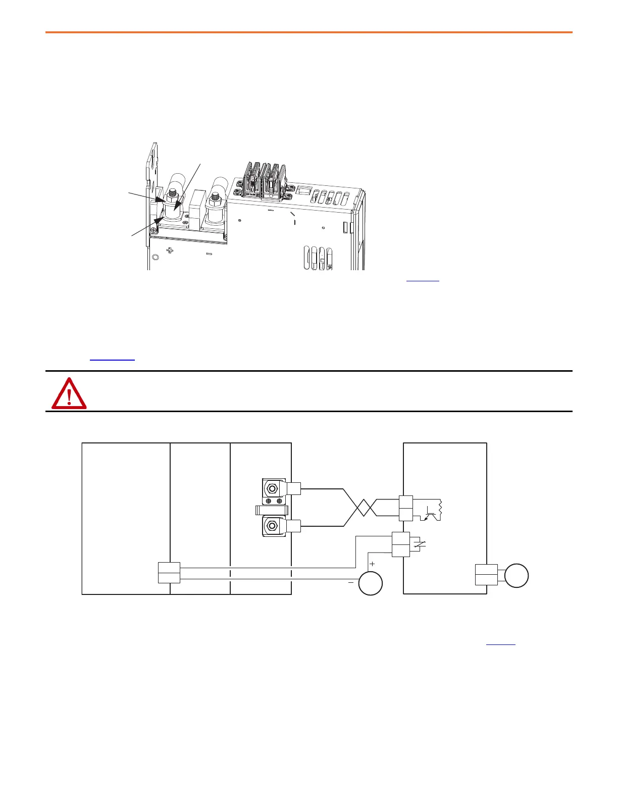
For drive systems that include the 2198-Pxxx DC-bus power supply and Powerohm PKBxxx or PWBxxx active shunts, make the active shunt
connections at the external DC-bus studs on accessory modules.
Accessory modules are equipped with spacers that slide onto M8 studs. When the system configuration includes external DC-bus and active
shunt connections, external DC-bus connections are made below the spacer and active shunt connections are made above the spacer.
Figure 18 - Active Shunt Connections
(1) An external active shunt can be wired to any of the accessory modules. See Kinetix 5700 Servo Drives User Manual, publication 2198-UM002, for more information on mounting and
accessory module example configurations. The 2198-CAPMOD-2240 capacitor module is preferred because it provides additional system capacitance.
(2) Position flexible bus-bars (when two accessory modules are used) below the DC-bus lug connections. The flexible bus-bars are used to parallel the extended DC-bus with another accessory
module in 208 A systems (not required when only one accessory module is used in 104 A systems). Flexible bus-bars are included with 2198-CAPMOD-DCBUS-IO extension modules or you can
order 2198-KITCON-CAPMOD2240 or 2198-KITCON-DCBUSCOND replacement kits.
For compatible Powerohm active shunts paired with 2198-Pxxx DC-bus power supplies, refer to Kinetix 5700 Servo Drives User Manual,
publication 2198-UM002
.
Figure 19 - 2198-Pxxx Power Supply with External Active Shunt (built-in brake resistor)
(1) Configure any available digital input as Shunt Thermal Switch OK.
(2) Powerohm PKB050 and PKB050-800 shunts require 120V AC between pins 9 and 10 to supply power to the cooling fans.
For more information on wiring to these Powerohm Bulletin PKBxxx active shunts, see the Knowledgebase Answer ID: 1082776.
ATTENTION: To avoid damage to the Kinetix 5700 drive system, wire the active shunt thermal switch to a digital input on the power supply
and configure the Shunt Thermal Switch OK function in the Studio 5000 Logix Designer® application.
2198-DCBUSCOND-RP312
2198-CAPMOD-2240 or
2198-CAPMOD-DCBUS-IO
(1)
Accessory Modules
(2198-CAPMOD-2240 capacitor module is shown)
Active Shunt
Lug Connections
(above spacer)
DC-bus
Lug Connections and
Flexible Bus-bars
(2)
(below spacer)
Spacer
DC+
DC–
120V AC
9
10
3
4
DC+
DC–
INx
COM
24V DC
(1)
(2)
2198-Pxxx
DC-Bus Power Supply
Powerohm
Bulletin PKBxxx-xxx
Active Shunt Module
Fault Contact
Digital Input
(IOD) Connector
External DC-bus
Resistor
4.6 m (15 ft) Maximum Cable Length
2198-xxxx-ERSx
Inverter
2198-CAPMOD-2240
Capacitor Module

 Loading...


