Rockwell Automation Publication MOTION-AT007A-EN-P - May 2020 55
Regenerative Bus Supply Configurations With Active Shunt Chapter 5
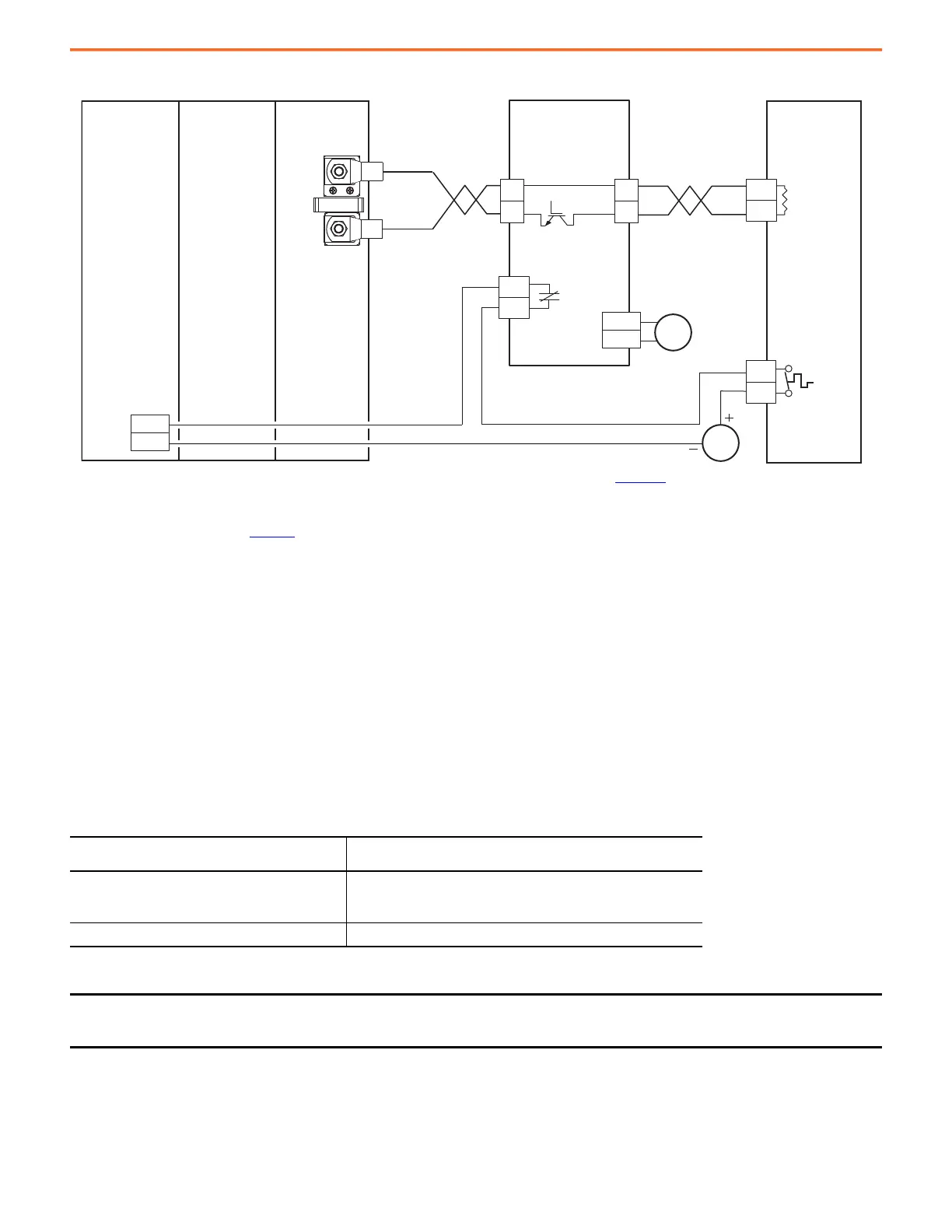
Figure 34 - 2198-RPxxx Bus Supply with External Active Shunt (external brake resistor)
(1) Configure any available digital input as Shunt Thermal Switch OK. See the Kinetix 5700 Servo Drives User Manual, publication 2198-UM002, for more information on configuring digital inputs.
(2) Powerohm PWB050 and PWB050-800 shunts require 120V AC between pins 9 and 10 to supply power to the cooling fans.
See Knowledgebase document 1082777 for more information on wiring to these Powerohm Bulletin PWBxxx active shunts.
Refer to the Powerohm documentation included with your Bulletin PKB or PWB shunt module to install, wire, and configure the module.
• To avoid nuisance thermal overload trips, configure Bulletin PKB and PWB active-shunt modules to the highest shunt turn-on voltage
setting. The recommended setting for Line Voltage Level Jumper is JP5.
• Configure Bulletin PKB and PWB active-shunt modules in Internal (automatic) mode. Unless an external enable signal is provided,
configure the Brake Enable Jumper in Internal (automatic) mode (JP6 is in the downward position).
Bus Supply Ground Jumper Setting
The 2198-RPxxx regenerative bus supply has a factory-installed ground screw for grounded-wye power distribution. The following table
summarizes the ground screw/jumper settings for the 2198-RPxxx regenerative bus supply.
Table 45 - Ground Jumper Settings for the Regenerative Bus Supply
Ground Configuration
2198-RPxxx
Regenerative Bus Supply
•Grounded (wye)
• Corner-grounded with isolation transformer
• Ungrounded with isolation transformer
Ground jumper installed (default setting)
Impedance grounded
Remove ground jumper
(1)
(1) When the regenerative bus supply ground jumper is removed, it can be permanently stored in threaded holes at the bottom of the chassis.
IMPORTANT If you have grounded-wye power distribution in your facility, or corner-grounded or ungrounded power with an isolation
transformer, do not remove the ground jumper from the regenerative bus supply. Remove the ground jumper when using
impedance-grounded power.
3
4
R1
R2
DC+
DC–
DC+
DC–
DC+
DC–
INx
COM
(1)
24V DC
120V AC
9
10
(2)
TS
TS
External DC-bus
Powerohm
External Passive
Shunt Module
Resistor
Thermal
Switch
Digital Input
(IOD) Connector
Powerohm
Bulletin PWBxxx-xxx
Active Shunt Module
4.6 m (15 ft)
Maximum Cable Length
9.1 m (30 ft)
Maximum Cable Length
2198-xxxx-ERSx
Inverter
Fault Contact
2198-RPxxx
Regenerative
Bus Supply
2198-CAPMOD-2240
Capacitor Module

 Loading...


