Rockwell Automation Publication MOTION-AT007A-EN-P - May 2020 73
Kinetix 5700 Accessory Modules Appendix B
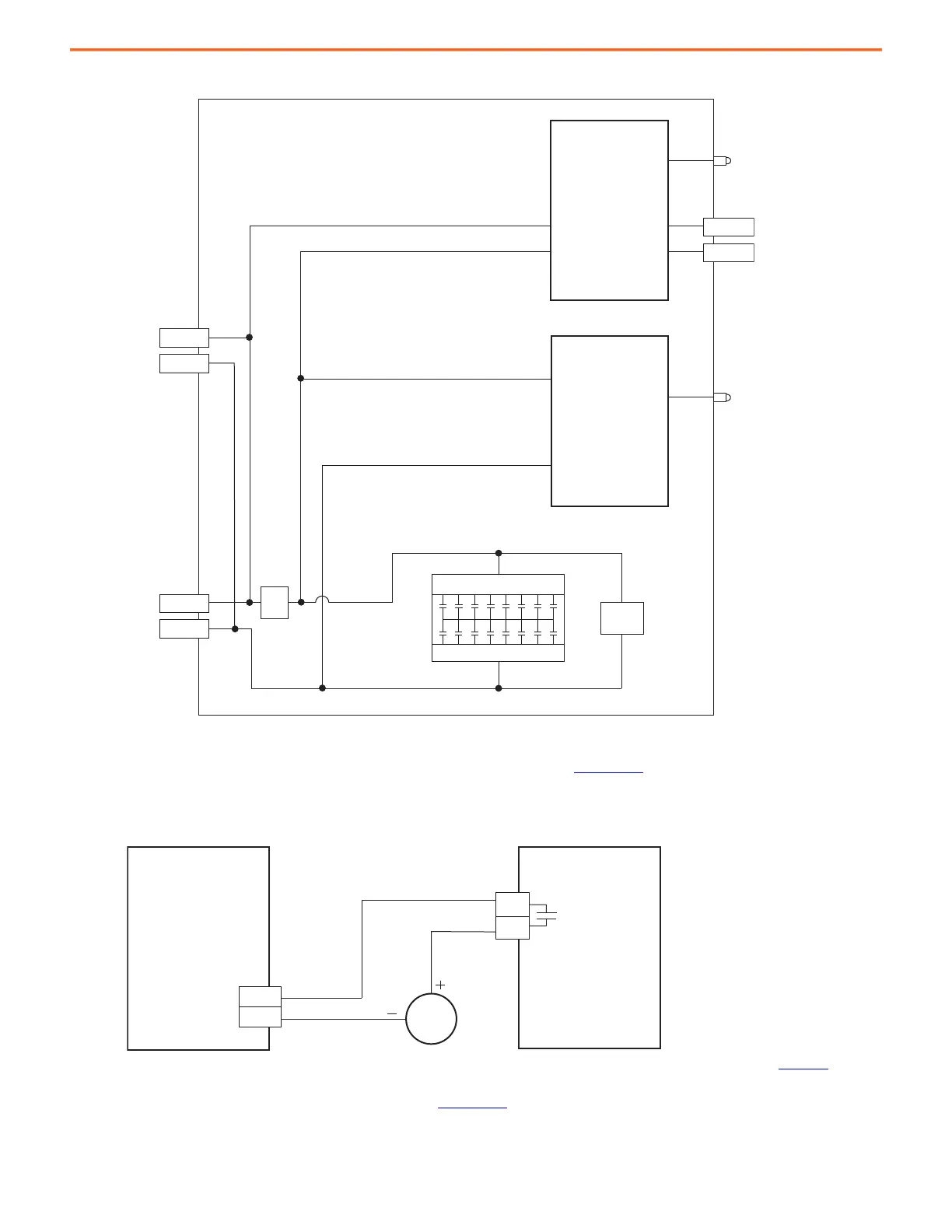
Figure 40 - Capacitor Module Block Diagram
You can configure either of the DC-bus power supply digital inputs as Bus Capacitor OK in the Logix Designer application to monitor the
Module Status output. Refer to the Kinetix® 5700 Servo Drives User Manual, publication 2198-UM002
, to see how the DC-bus power supply
Digital Inputs category is configured.
Figure 41 - DC-bus Power Supply with Capacitor Module
(1) Configure either of two digital inputs as Bus Capacitor OK. For DC-bus power supply configurable functions, see Kinetix 5700 Servo Drives User Manual, publication 2198-UM002.
Refer to the Kinetix 5700 Servo Drives User Manual, publication 2198-UM002, for more information on accessory module installation.
DC–
DC+
DC+
DC–
DC–
DC+
DC–
MS
MS
DC-bus Input
Link Connector
DC-bus Output
Lug Connector
Module Status
Status Indicator
DC-bus Status
Status Indicator
Module Status
(MS) Connector
Fuse Detection
DC-bus Detection
Capacitor Bank
Bleeder
Resistor
Fuse
2198-Pxxx
DC-bus Power Supply
2198-CAPMOD-2240
Capacitor Module
Module Status (MS)
Connector
Digital Input
(IOD) Connector

 Loading...


