EasyManuals Logo

Rockwell Automation Allen-Bradley PanelView 5510 Series User Manual

Rockwell Automation Allen-Bradley PanelView 5510 Series
112 pages
To Next Page IconTo Next Page
To Previous Page IconTo Previous Page
Page #30 background imageLoading...
Page #30 background image
30 Rockwell Automation Publication 2715P-UM001C-EN-P - March 2019
Chapter 2 Install the PanelView 5510 Terminal
Figure 5 - Mounting Lever Orientation and Lock Sequence
ERR
STS
1
2
1
2
5
24
6
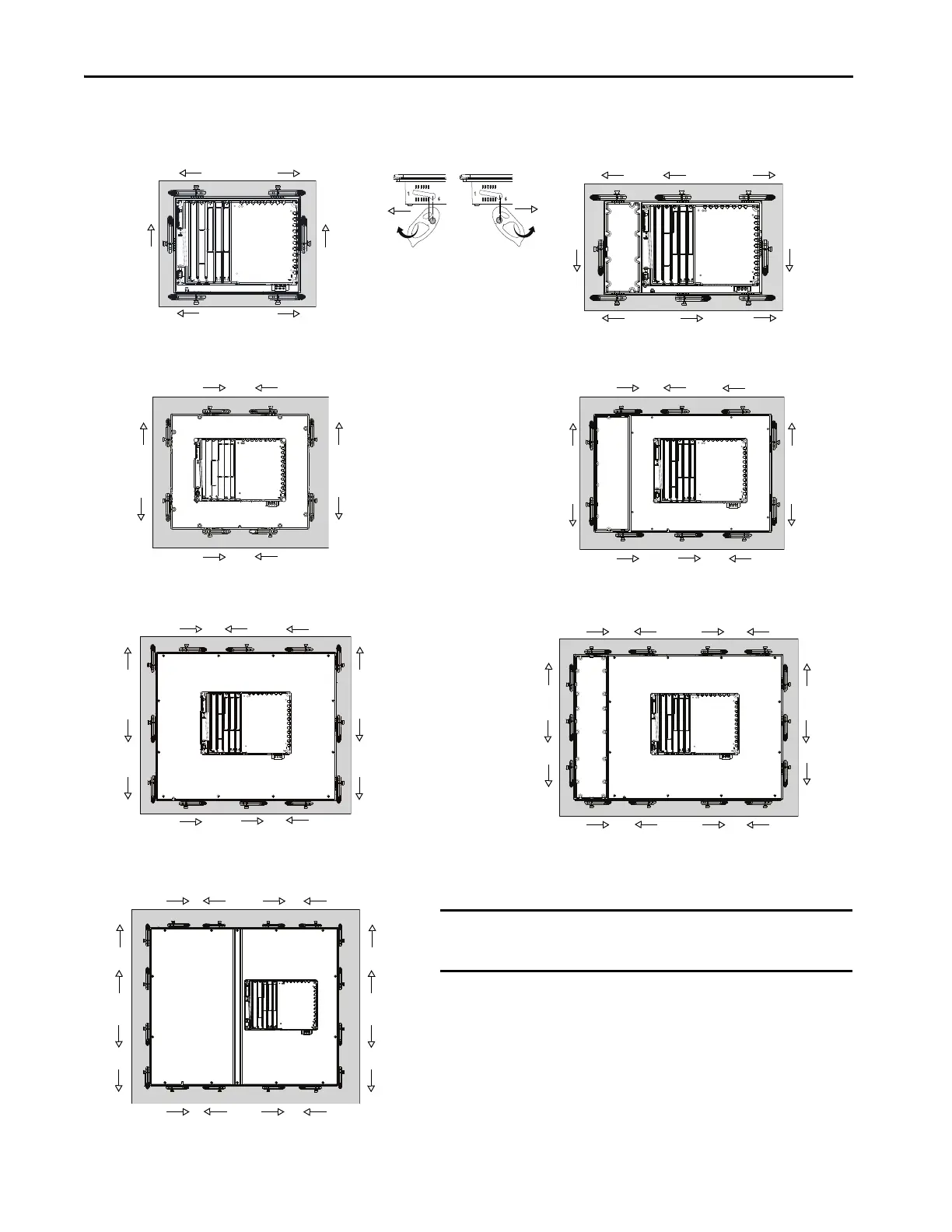
6.5-in. Touch Only and 7-in. Touch Only - 6 Levers
6.5-in. Keypad and Touch - 8 Levers
2
7
4
8
8
29
3
10 1
7
5
4
5
9-in. and 10.4-in. Touch Only - 8 Levers
10.4-in. Keypad and Touch, 12.1-Touch Only - 10 Levers
3
1
6
24
5
6
8
7
3
1
6
3
1
29 4
6
12
8
11
5
82 46
11
13
9
10
14
12
15-in. Keypad and Touch - 14 Levers
53 17
1
10
3
7
15-in. Touch Only- 12 Levers
19-in. Touch Only- 16 Levers
53 1 7
82 4 6
11
13
9
15
10
16
12
14
IMPORTANT
The mounting lever orientations that are shown are required to maintain
NEMA, UL Type, and IP seals. If you require a NEMA, UL Type, or IP seal, do
not use a mounting lever in another orientation than shown.

Table of Contents

Questions and Answers:

Question and Answer IconNeed help?

Do you have a question about the Rockwell Automation Allen-Bradley PanelView 5510 Series and is the answer not in the manual?

Rockwell Automation Allen-Bradley PanelView 5510 Series Specifications

General IconGeneral
BrandRockwell Automation
ModelAllen-Bradley PanelView 5510 Series
CategoryTouch terminals
LanguageEnglish

Related product manuals