32 Rockwell Automation Publication 2715P-UM001C-EN-P - March 2019
Chapter 2 Install the PanelView 5510 Terminal
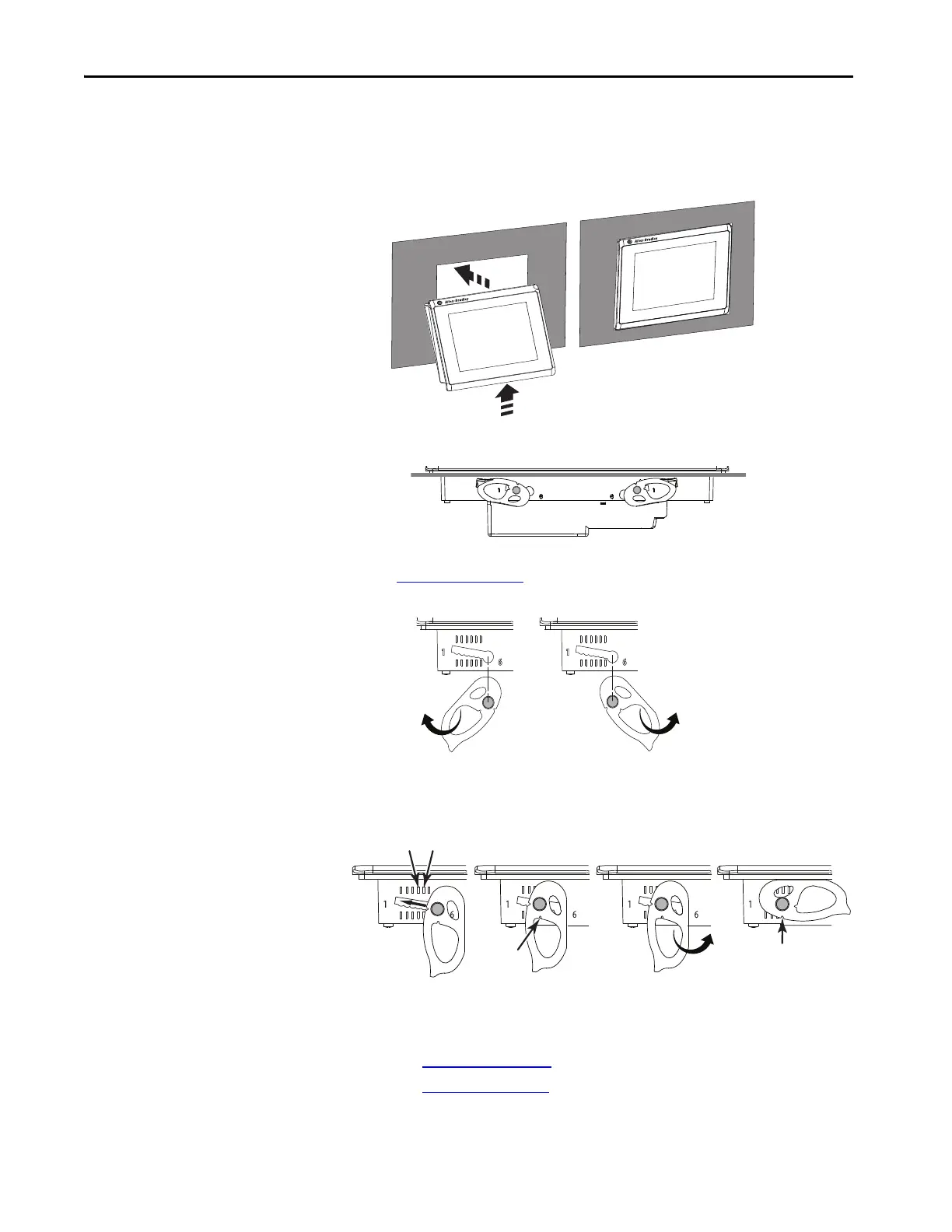
b. Tilt the terminal toward the panel cutout and guide upward into the
cutout. Make sure that the levers stay intact.
c. Pull the top of the terminal toward you to verify that the levers are still
intact and the terminal is stabilized in the panel.
d. Insert the remaining levers in the slots by using the orientations in
Figure 5 on page 30
that are correct for your terminal.
The direction that you rotate the levers varies for each terminal size.
4. Slide and rotate each lever to a notch that is one or two positions greater
than the final lock position. Start with the first lever in the sequence.
For example, if the final lock position is 3, slide the lever to notch 4 or 5.
a. See Table 13 on page 28
to get the final lock position of the levers.
b. See Figure 5 on page 30
to get the locking sequence.
c. Rotate each lever until its flat side comes in contact with the panel.
TIP The levers help prevent the terminal from falling out of the panel.
TIP To help position the levers and identify the final slot position, use the
alignment marks or previous marks you made on the bezel.
54
Inner
Notch
Outer
Notch
Flat Side
of Lever

 Loading...


