EasyManuals Logo

Rockwell Automation Allen-Bradley PowerFlex 7000 User Manual

Rockwell Automation Allen-Bradley PowerFlex 7000
434 pages
To Next Page IconTo Next Page
To Previous Page IconTo Previous Page
Page #300 background imageLoading...
Page #300 background image
300 Rockwell Automation Publication 7000L-UM301F-EN-P - March 2020
Chapter 5 Component Definition and Maintenance
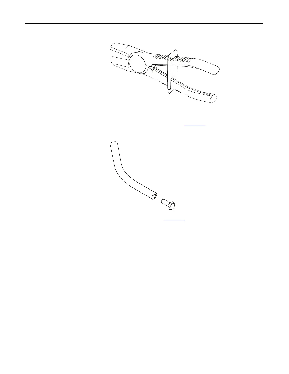
Figure 247 - Flow Restrictor Clamp
Also required are two (2) pieces of 3/8" hose (included) in spare parts kit
and four (4) M10 bolts with a length from 10 to 30 mm for use as plugs in
the 3/8" hose (not included). See Figure 248
. M10 bolts must be clean.
Figure 248 - Flow Stopper for Servicing (2 required)
6. Insert the 2 clamps per Figure 249 on the 3/4-inch (19-mm) silicon hoses
to isolate flow between the vertical manifolds and the horizontal
manifolds of the converter modules.

Table of Contents

Other manuals for Rockwell Automation Allen-Bradley PowerFlex 7000

Questions and Answers:

Question and Answer IconNeed help?

Do you have a question about the Rockwell Automation Allen-Bradley PowerFlex 7000 and is the answer not in the manual?

Rockwell Automation Allen-Bradley PowerFlex 7000 Specifications

General IconGeneral
BrandRockwell Automation
ModelAllen-Bradley PowerFlex 7000
CategoryDC Drives
LanguageEnglish

Related product manuals