Rockwell Automation Publication 7000L-UM301F-EN-P - March 2020 301
Component Definition and Maintenance Chapter 5
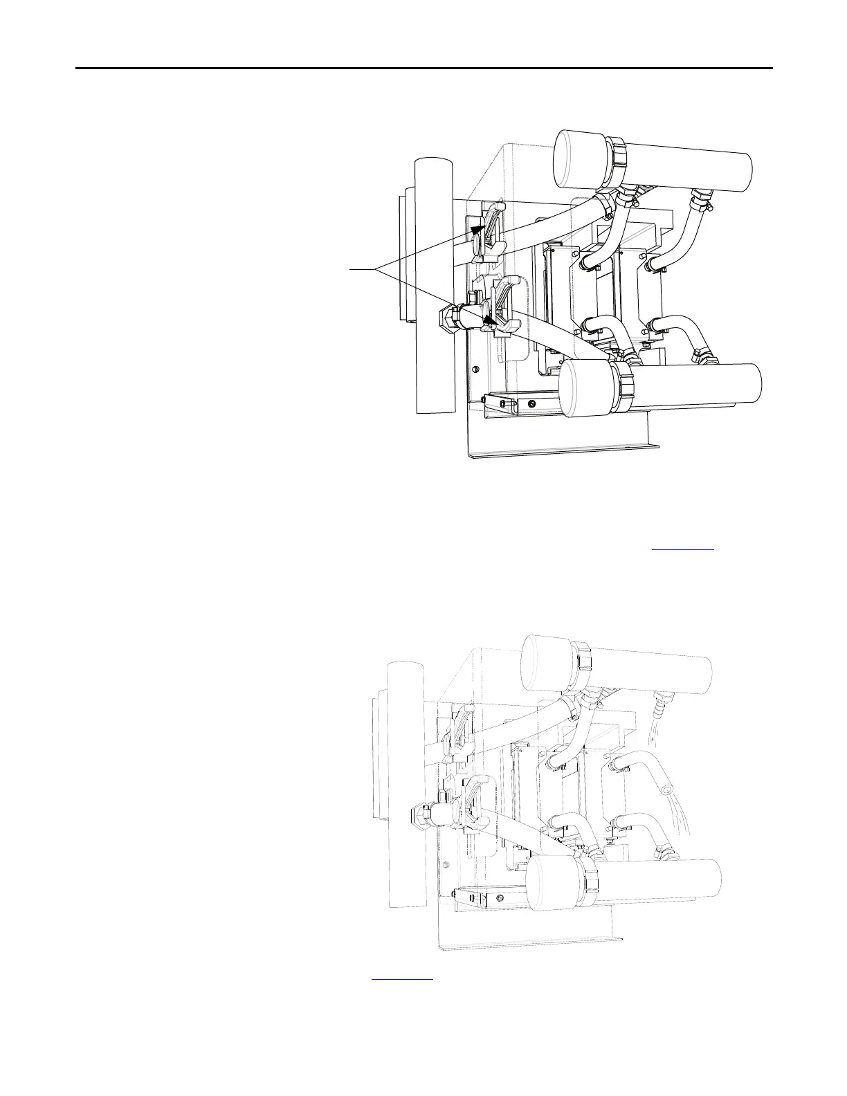
Figure 249 - Converter PowerCage Module (Service – per Step 6)
Loosen the hose clamp of the top hose of the outlet manifold of the chill
block to be serviced. Slide the hose clamp toward the chill block.
7. Have a hose plug assembly and a M10 bolt ready. Per Figure 250
, pull the
hose from the upper manifold hose barb and collect the fluid in a
container.
Figure 250 - Converter PowerCage Module (Service – per Step 7)
8. Per Figure 251, insert the hose plug on the hose barb of the upper
manifold. Insert a M10 bolt in the end of the chill block hose. Note that
there may still be limited fluid leakage during this procedure.

 Loading...


