88 Rockwell Automation Publication 20D-PM001D-EN-P - March 2019
Chapter 2 Programming and Parameters
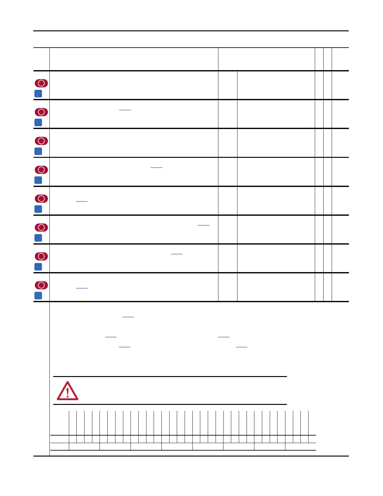
No. Name
Description
Values
Linkable
Read-Write
Data Type
502 Rotor Resistance
Displays rotor resistance, as determined by the auto-tune procedure. Scaled to percent of rated motor
impedance. Do not change this value.
Default:
Min/Max:
Units:
Scale:
1.00
0.00/100.00
%
100 = 8192
RW 16-bit
Integer
503 Current Reg BW
Sets the bandwidth for the current regulator. Par 402 [PWM Frequency] limits the maximum value. Reducing
the value reduces current regulator over-shoot.
Default:
Min/Max:
Units:
600
100/30000
rad/s
RW 16-bit
Integer
504 PM AbsEncd Offst
Determined by auto-tune procedure.
Default:
Min/Max:
0
0/65535
RW 16-bit
Integer
505 PM TestWait Time
Defines the time interval used for the automated measurement of Par 504 [PM AbsEncd Offst] for a Permanent
Magnet (PM) motor.
Default:
Min/Max:
Units:
2000
500/5000
ms
RW 16-bit
Integer
506 PM Test Idc Ramp
Defines the ramp rate of the Flux Producing (d-axis) current reference that is used for the automated
measurement of Par 504 [PM AbsEncd Offst] for a Permanent Magnet (PM) motor.
Default:
Min/Max:
Units:
Scale:
0.1
0.0/195.3
%/ms
x 10
RW 16-bit
Integer
507 PM Test FreqRamp
Defines the ramp rate of the frequency reference that is used for the automated measurement of Par 504 [PM
AbsEncd Offst] for a Permanent Magnet (PM) motor.
Default:
Min/Max:
Units:
Scale:
0.1
0.0/195.3
%/ms
x 10
RW 16-bit
Integer
508 PM Test Freq Ref
Defines the frequency reference that is used for the automated measurement of Par 504 [PM AbsEncd Offst] for
a Permanent Magnet (PM) motor.
Default:
Min/Max:
Units:
Scale:
10.0
-/+799.9
%
x 10
RW 16-bit
Integer
509 PM Test I Ref
Defines the amplitude of the Flux Producing (d-axis) current reference that is used for the automated
measurement of Par 504 [PM AbsEncd Offst] for a Permanent Magnet (PM) motor.
Default:
Min/Max:
Units:
Scale:
30.0
0.0/799.9
%
x 10
RW 16-bit
Integer
510 FVC Mode Config
Configures Field Oriented Control (FOC) operation.
• Bit 4 “SlipTuneDone” when set, the value in Par
486 [Rated Slip Freq] is used as the slip gain before the slip regulator becomes active, after power is cycled, or when the drive is reset by the
system. When the Slip Tune is completed, this bit will be automatically be set and Par 486 will be updated.
• Bit 7 “Ids Comp En” setting this bit runs the Ids test, to establish the initial flux current level for the motor, and the inertia test (even if already run).
• Bit 12 “SlipRsCompEn” when set, the stator resistance will be compensated based on the output of the slip regulator.
• Bit16 “ManuCurOffst” when set, Par
453 [Iu Offset] is used as the phase U current feedback offset value and Par 454 [Iw Offset] is used as the phase W current feedback offset value. When this bit
is not set (default) the phase U and W current feedback offset values are automatically updated when the drive is in a stop condition except during the first 10 seconds of the stop condition.
• Bit17 “ManuVltOffst” when this bit is set, Par
549 [Vuv Fdbk Offset] is used as the UV voltage feedback offset value and Par 550 [Vvw Fdbk Offset] is used as the VW voltage feedback offset value.
• Bit 23 “SyncTrans En” when set (default), the synchronous transfer algorithm using voltage feedback data is active.
• Bit 26 “SlipGnLimAct” when set = 0 (default), set slip regulator output (SlipGain) to latched SlipGain. When set =1, set SlipGain to Max SlipGain when SlipGain is in Max SlipGain limit, or set
SlipGain to Min SlipGain when SlipGain is in Min SlipGain limit.
Notes: Bit changes were made for firmware version 2.003. Bits 10 and 11 were added for firmware version 3.001. Changed bit 3 from “Reserved” to “FastFluxDsbl” for firmware version 3.003. Added
bits 4, 7, 12, 16, 17, and 23 for firmware version 4.001. Added Bit 26 for firmware version 6.001.
ATTENTION: Do not modify this parameter. Motor/Drive instabilities and damage may result.
Options
Reserved
Reserved
Reserved
Reserved
Reserved
SlipGnLimAct
Reserved
Reserved
SyncTrans En
SrLss RdThru
VltMinorLpEn
SoftAdptGain
Reserved
Reserved
ManuVltOffst
ManuCurOffst
LwSpdRflctWv
Slip Reg En
SlipGain Est
SlipRsCompEn
SlipPrloadEn
SlipSlewRtEn
ReflWaveComp
BusGain Comp
Ids Comp En
Flux Reg Use
Flux Reg En
SlipTuneDone
FastFluxDsbl
Reserved
Reserved
Reserved
Default xxxxxxxx1010xx000110001101100xxx
Bit 313029282726252423222120191817161514131211109876543210
0 = False
1 = True
 Loading...


