Rockwell Automation Publication 750-TG101A-EN-P - June 2022 101
Chapter 5 Frame 6 Renewal Kits Installation
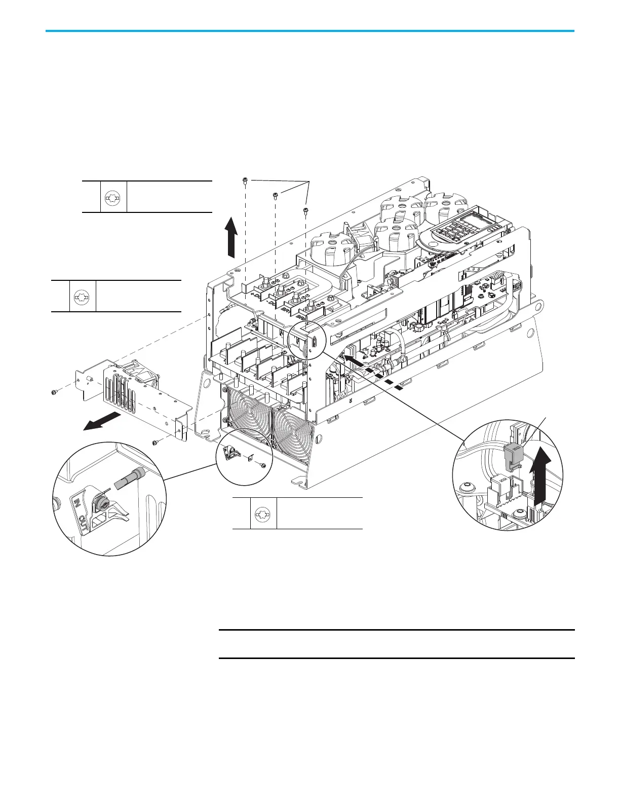
4. For AC input drives, record the PE-A jumper position and remove the
PE-A jumper wire from the jumper assembly.
5. Remove the M4 x 8 mm slotted-Torx screw that secures the PE-A jumper
assembly to the bracket and remove the jumper assembly.
6. Remove the three M4 x 10 mm slotted-Torx screws that secure the fan
assembly to the chassis.
7. Remove the two M4 x 8 mm slotted-Torx screws that secure the fan
assembly to the chassis and remove the fan assembly, partially.
8. Disconnect the fan power wire-harness connector P5 from J5 on the
power interface circuit board and remove the fan assembly.
Install the Lower Stirring Fan Assembly
Install the lower stirring fan assembly in the reverse order of removal.
7
M4 x 8 mm
T20 or F - 6.4 mm (0.25 in.)
2.6 N
•m (23.0 lb•in)
5
M4 x 8 mm
T20 or F - 6.4 mm (0.25 in.)
2.6 N
•m (23.0 lb•in)
6
M4 x 10 mm
T20 or F - 6.4 mm (0.25 in.)
2.6 N
•m (23.0 lb•in)
5
6
4
7
7
8
P5
PE-A
IMPORTANT Verify that the PE-A jumper wire harness is reconnected in the same
position as before removal.

 Loading...


