32 Rockwell Automation Publication 750-TG101A-EN-P - June 2022
Chapter 3 Component Inspection and Tests
7. For frames 6 and 7, inspect the power interface, and AC precharge or DC
precharge circuit boards. If any components, particularly the resistors,
show evidence of burn marks or breakage, replace the circuit board
without further testing.
• For frame 6 power interface circuit board, see page 106
.
• For frame 6 AC precharge circuit board, see page 113
.
• For frame 6 DC precharge circuit board, see page 119
.
• For frame 7 power interface circuit board, see page 151
.
• For frame 7 AC precharge circuit board, see page 161
.
• For frame 7 DC precharge circuit board, see page 170
.
Forward and Reverse Biased
IGBT/Diode Tests
Follow these steps to perform forward and reverse biased IGBT/diode tests on
the power modules. A failed test indicates damage to the components in the
power modules and requires replacement of the drive.
1. Review the Product Advisories
on page 11.
2. Remove power from the system. See Remove Power from the System
on
page 12.
3. Select the “Diode Test” mode on the digital multi-meter and complete the
forward and reverse biased diode tests on the power module for your
product frame size. See Figure 1 on page 13
and Figure 2 on page 14 for
terminal locations and identification.
4. If the product fails the measurements that are identified in Table 1
or
Table 2
, replace the drive.
5. Complete the procedures in Appendix A on page 179
before placing the drive
back into service.
IMPORTANT The actual voltage readings can vary depending upon your equipment. If
your readings are not near the indicated values in Table 1
and Table 2 verify
that the actual voltage that is measured is consistent for each phase of the
power module.
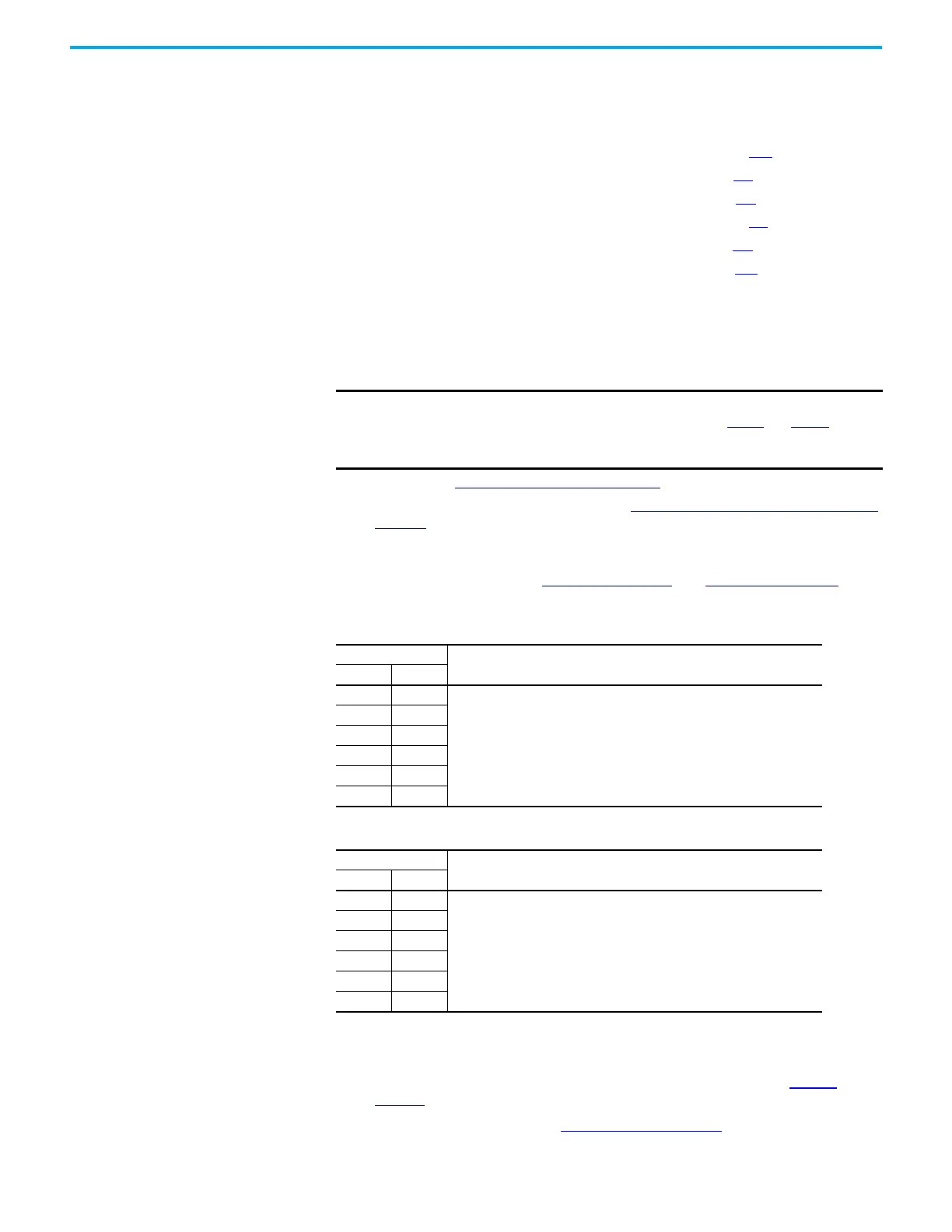
Table 1 - Forward Biased Diode Tests on the Converter IGBT Assembly
Meter Leads
Nominal Meter Reading
+-
–DC U/T1
0.36V
–DC V/T2
–DC W/T3
U/T1 +DC
V/T2 +DC
W/T3 +DC
Table 2 - Reverse Biased Diode Tests on the Converter IGBT Assembly
Meter Leads
Nominal Meter Reading
+–
U/T1 –DC
“.0L” (open circuit)
(1)
(1) Residual voltage on the DC bus capacitors can affect this reading. If the capacitors are discharged (less than 1 volt),
the meter initially shows a low voltage. This voltage reading is the residual bus voltage plus the drop through the low
side diodes. The meter gradually charges the bus, and the voltage slowly increases, until eventually the meter
switches to “.OL”. This increase can take several minutes to occur.
V/T2 –DC
W/T3 –DC
+DC U/T1
+DC V/T2
+DC W/T3

 Loading...


