Rockwell Automation Publication 750-TG101A-EN-P - June 2022 129
Chapter 6 Frame 7 Renewal Kits Installation
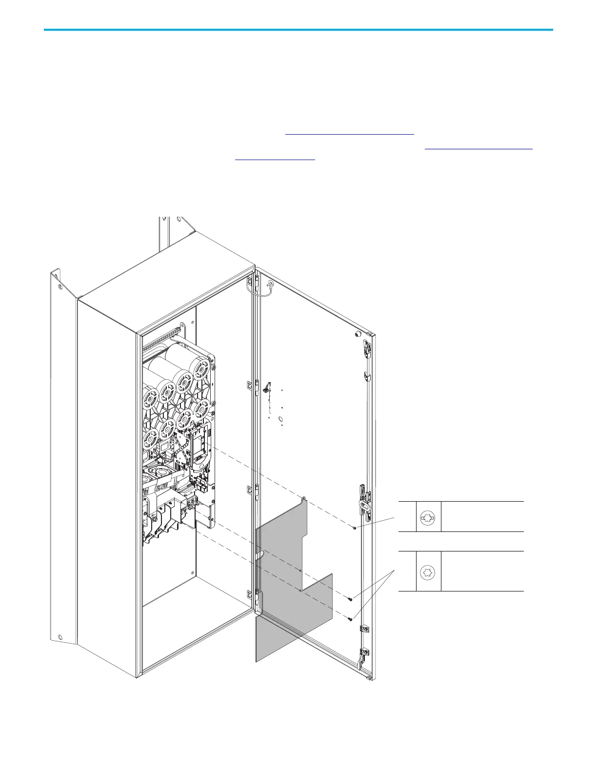
Remove the Protective
Guard (IP54, NEMA/UL Type
12 Enclosure)
Remove the protective guard from an IP54, NEMA/UL Type 12 enclosure to
access the power terminals, stirring fan, and power interface circuit board.
Remove the Protective Guard (IP54, NEMA/UL Type 12 Enclosure)
Follow these steps to remove the protective guard from an IP54, NEMA/UL
Type 12 enclosure.
1. Review the Product Advisories
on page 11.
2. Turn off and lock-out incoming power. See Remove Power from the
System on page 12.
3. Remove the M4 x 8 mm slotted-Torx screw that secures the upper guard
to the standoff on the drive chassis.
4. Remove the two M5 x 12 mm Torx screws that secure the lower guard to
the chassis terminal support bracket and remove the guard.
Install the Protective Guard (IP54, NEMA/UL Type 12 Enclosure)
Install the protective guard in the reverse order of removal.
3
M4 x 8 mm
T20 or F - 6.4 mm (0.25 in.)
2.6 N
•m (23.0 lb•in)
4
M5 x 12 mm
T25
a. 2.6 N
•m (23.0 lb•in)
b. 6.0 N•m (53 lb•in)

 Loading...


