144 Rockwell Automation Publication 750-TG101A-EN-P - June 2022
Chapter 6 Frame 7 Renewal Kits Installation
Stirring Fan Assembly
Replacement
Replacement kit catalog numbers: SK-RT-STIRFAN1-F7,
SK-RT-STIRFAN1-F7-XT
These kits can be used for all enclosure types.
Remove the Stirring Fan Assembly
Follow these steps to replace the stirring fan assembly for a frame 7 drive.
1. Review the Product Advisories
on page 11.
2. Turn off and lock-out incoming power. See Remove Power from the
System on page 12.
3. Access the drive interior:
• For IP00, NEMA/UL Open Type, IP21, NEMA/UL Type 1 and flange,
NEMA/UL Type 4X/12 back enclosures, remove the cover. See Remove
the Cover on page 128.
• For IP54, NEMA/UL Type 12 enclosures, open the enclosure and
remove the protective guard. See Remove the Protective Guard (IP54,
NEMA/UL Type 12 Enclosure) on page 129.
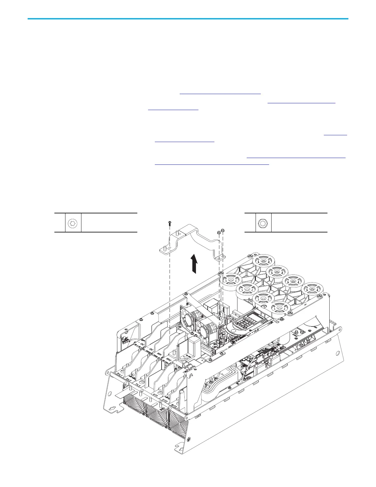
4. If the brake bus bar (BR1) is installed, complete these steps:
a. Remove the two M6 hexagonal nuts that secure the upper end of the
bus bar to the drive.
b. Remove the M5 x 16 mm Torx screw that secures the lower end of the
bus bar to the BR1 terminal and remove the bus bar from the drive.
4a
M6
10 mm
5.2 N
•m (46.0 lb•in)
4a
4b
4b
M5 x 16 mm
T25
5.2 N
•m (46.0 lb•in)

 Loading...


