150 Rockwell Automation Publication 750-TG101A-EN-P - June 2022
Chapter 6 Frame 7 Renewal Kits Installation
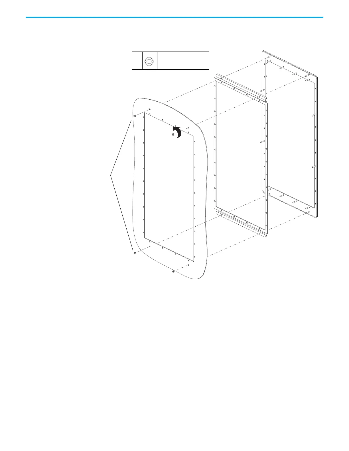
14. Remove the four M5 x 0.8 hexagonal nuts that secure the rear gasket,
support brackets, and flange to the panel mount surface, and remove the
gasket, brackets, and flange. Discard the gasket.
Install the Flange Gasket
Install the gaskets, support brackets, and flange in the reverse order of
removal. Follow these steps to install the hardware that secures the drive
chassis to the panel mount surface.
1. Install the M5 x 0.8 hexagonal nuts that secure the drive chassis to the
flange in the sequence shown here.
2. Install the M5 x 25 mm slotted-Torx screws that secure the drive chassis
to the flange in the sequence shown here.
14
14
M5 x 0.8
8 mm
4.5 N
•m (40.0 lb•in)

 Loading...


