Rockwell Automation Publication 750-TG101A-EN-P - June 2022 143
Chapter 6 Frame 7 Renewal Kits Installation
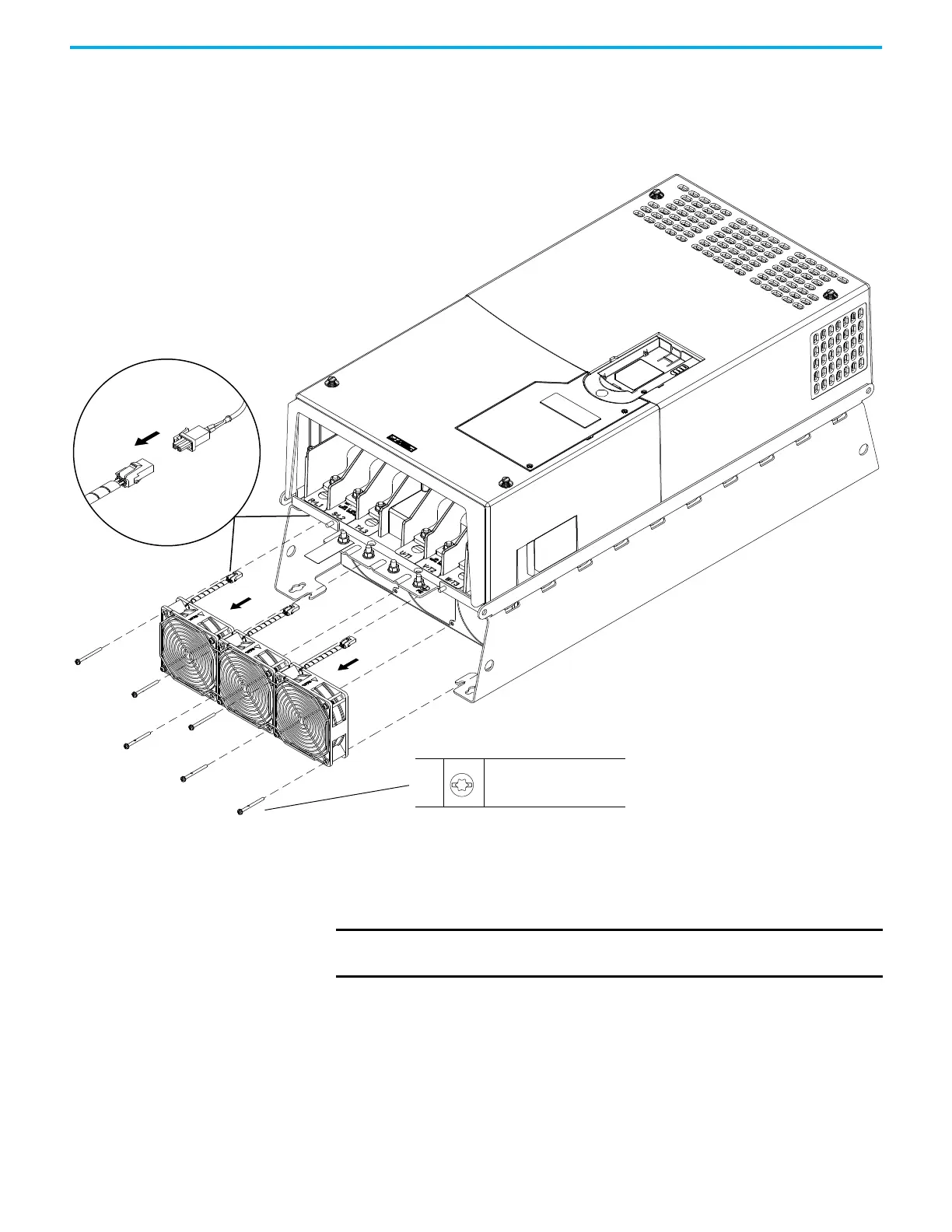
4. Remove the four M6 x 50 mm slotted-Torx screws that secure the fan
assembly to the chassis and remove the fan assembly partially from the
chassis.
5. Disconnect the three fan-assembly power wire harness connectors from
the three connectors inside the chassis and remove the fan assembly.
Install the Heatsink Fan Assembly
Install the heatsink fan assembly in the reverse order of removal.
5 (Quantity 3)
4
M6 x 50 mm
T30
1.36 N
•m (12.0 lb•in)
Wire Harness Connectors for the IP00, NEMA/UL Open Type
and IP21, NEMA/UL Type 1 Fan Assemblies Shown.
IP00, NEMA/UL Open Type Drive Shown.
IMPORTANT Before installation, remove the protective covers from the fan assembly
wire harness connectors.

 Loading...


