Rockwell Automation Publication 750-TG101A-EN-P - June 2022 113
Chapter 5 Frame 6 Renewal Kits Installation
AC Precharge Circuit Board
(400/480V) Replacement
Replacement kit catalog number: SK-RT-ACPC-CDF6
Remove the AC Precharge Circuit Board (400/480V)
Follow these steps to remove the AC precharge circuit board.
1. Review the Product Advisories
on page 11.
2. Turn off and lock-out incoming power. See Remove Power from the
System on page 12.
3. Access the drive interior:
• For IP00, NEMA/UL Open Type, IP21, NEMA/UL Type 1, and flange,
NEMA/UL Type 4X/12 back enclosures, remove the drive cover. See
Remove the Cover
on page 83.
• For IP54, NEMA/UL Type 12 enclosures, open the enclosure door and
remove the protective guard. See Remove the Protective Guard (IP54,
NEMA/UL Type 12 Enclosure) on page 84.
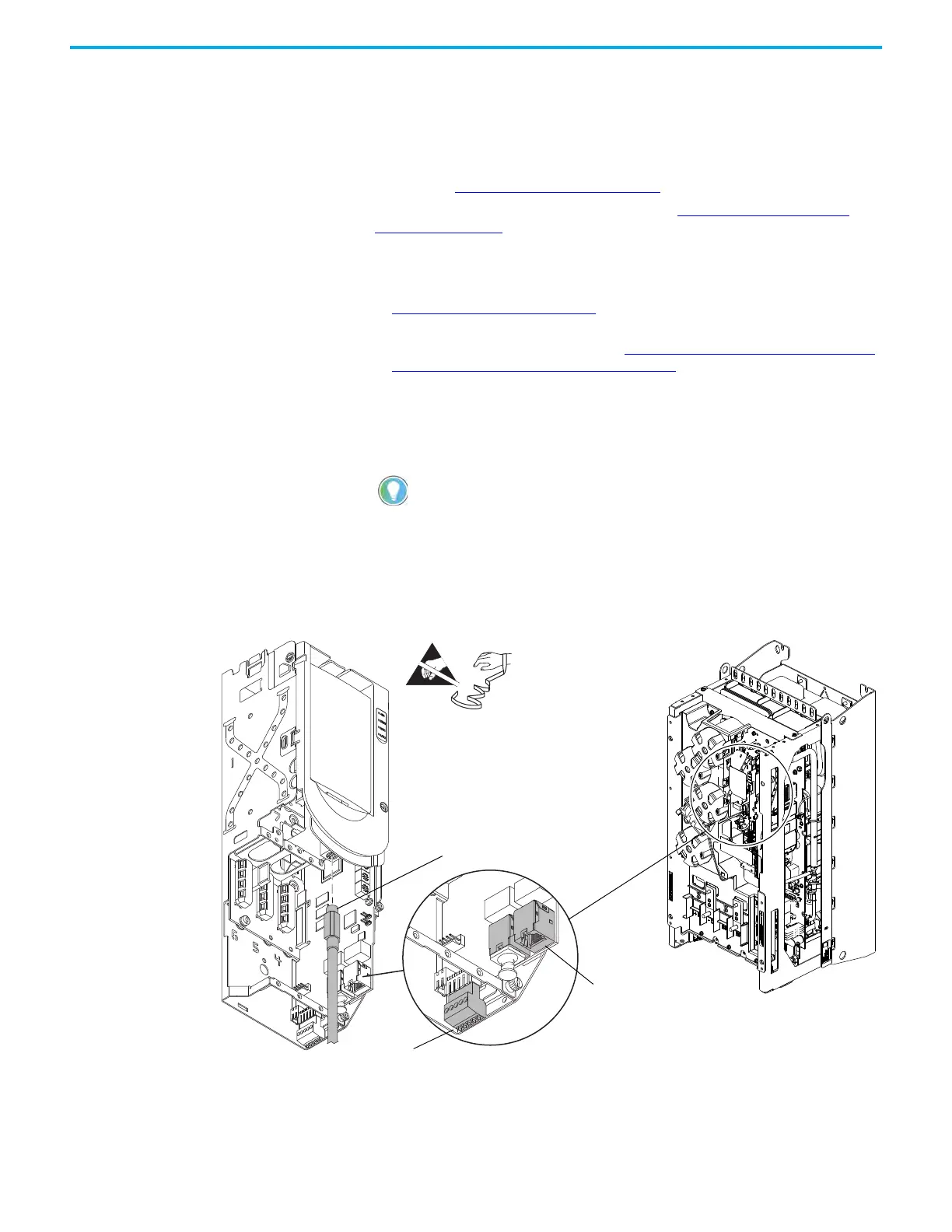
4. To prepare the control pod for removal from the drive, complete these
steps:
a. If used, disconnect the HIM DPI cable from the connector (port 2) on
the HIM cradle.
b. Disconnect any cables from the Ethernet connectors on the bottom of
the main control board in the control pod.
c. If used, disconnect the plug-in terminal block (TB1) on the bottom of
the main control board.
d. If an option module is installed, disconnect any I/O wiring terminal
blocks (not shown in image).
5. Remove the M4 x 12 mm Torx screw that secures the PE-B jumper cover
to the capacitor cover and remove the jumper cover.
If a cable is not connected to the DPI port on the HIM cradle, be sure to leave the
protective cover installed.
Control Pod Shown Separated
from the Drive for Clarity Only.
4b
4c
4a

 Loading...


