Rockwell Automation Publication 750-TG101A-EN-P - June 2022 107
Chapter 5 Frame 6 Renewal Kits Installation
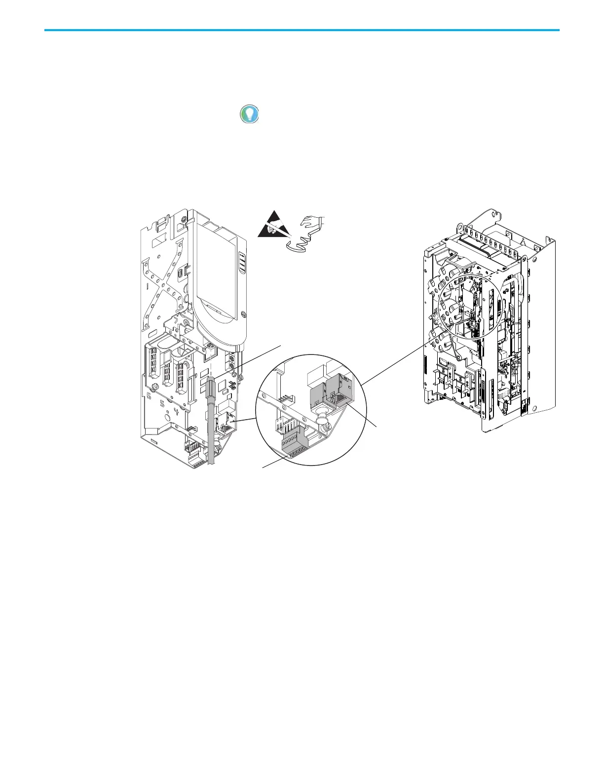
4. To prepare the control pod for removal from the drive, complete these
steps:
a. If used, disconnect the HIM DPI cable from the connector (port 2) on
the HIM cradle.
b. Disconnect any cables from the Ethernet connectors on the bottom of
the main control board in the control pod.
c. If used, disconnect the plug-in terminal block (TB1) on the bottom of
the main control board.
d. If an option module is installed, disconnect any I/O wiring terminal
blocks (not shown in image).
5. Remove the M4 x 12 mm Torx screw that secures the PE-B jumper cover
to the capacitor cover and remove the jumper cover.
6. Note the PE-B jumper position and if the PE-B jumper is in the OFF
position, remove the jumper wire from the connector on the power
interface circuit board.
7. Below the control pod, disconnect the ribbon cable connector from
connector J1 on the power interface circuit board.
8. If a torque accuracy module (TAM) is installed, complete steps a and b.
a. Disconnect the wire harness connector P4 from J4 on the power
interface circuit board.
b. Disconnect the wires from connectors U, V, and W on the power
interface circuit board.
9. Disconnect the lower stirring fan power wire-harness connector P5 from
J5 on the power interface circuit board.
10. Disconnect the upper stirring fan power wire-harness connector P6 from
J6 on the power interface circuit board.
11. For AC input drives, note the PE-A jumper position and remove the
PE-A jumper wire from the jumper assembly.
If a cable is not connected to the DPI port on the HIM cradle, be sure to leave the
protective cover installed.
Control Pod Shown Separated
from the Drive for Clarity Only.
4b
4c
4a

 Loading...


