Rockwell Automation Publication 750-TG101A-EN-P - June 2022 115
Chapter 5 Frame 6 Renewal Kits Installation
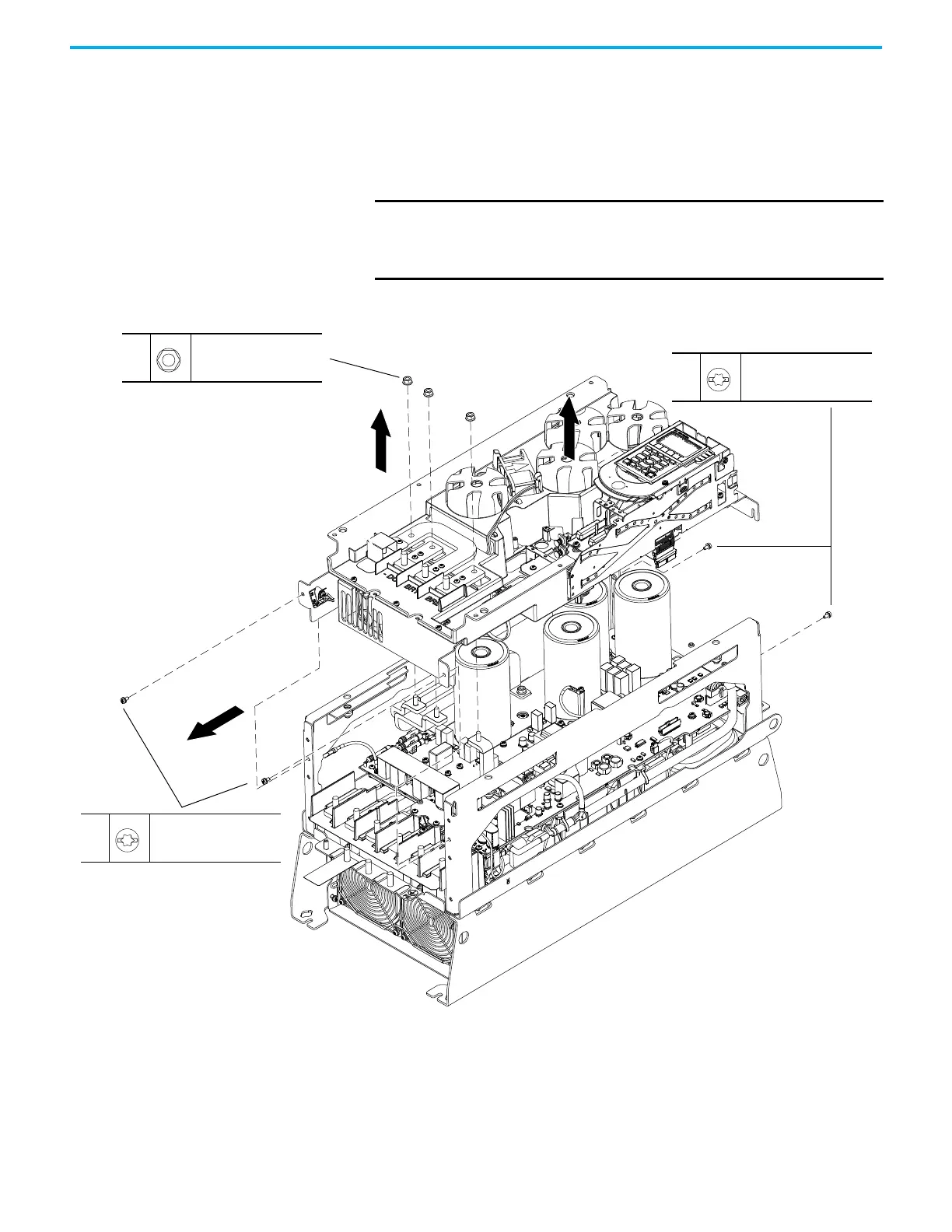
12. For drives with DC bus bars or a dynamic brake option installed, remove
the applicable M6 hexagonal nuts from the bus bar terminals.
13. Loosen the two M4 x 8 mm slotted-Torx screws that secure the upper
chassis bracket to the chassis and remove the bracket.
14. Remove the two M4 x 8 mm slotted-Torx screws that secure the lower
stirring fan assembly to the chassis.
15. Lift the bus capacitor cover, upper support bracket, and lower stirring
fan assembly off the drive.
IMPORTANT An edge connector on the main control circuit board in the control
pod is connected to the power interface circuit board below with a
ribbon cable. The ribbon cable fits through an opening in the back of
the control pod chassis.
13
M4 x 8 mm
T20 or F - 6.4 mm (0.25 in.)
2.6 N
•m (23.0 lb•in)
12
M6
10 mm
5.2 N
•m (46.0 lb•in)
14
M4 x 8 mm
T20 or F - 6.4 mm (0.25 in.)
2.6 N
•m (23.0 lb•in)
Loosen Only. Shown Removed for Clarity Only.
15
15

 Loading...


