Rockwell Automation Publication 750-TG101A-EN-P - June 2022 117
Chapter 5 Frame 6 Renewal Kits Installation
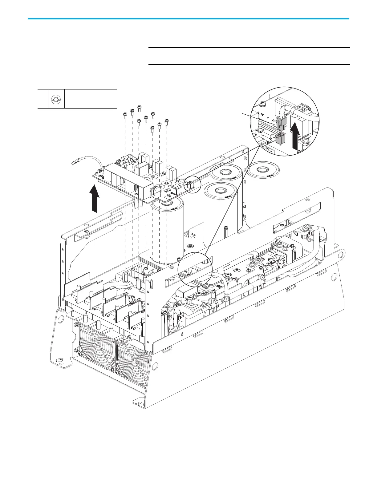
17. Disconnect the precharge wire harness connector P10 from connector
J10 on the AC precharge circuit board.
18. Remove the nine M4 x 12 mm slotted -Torx screws and remove the board
and plastic board support.
IMPORTANT The back side of the AC precharge circuit board contains solid gate
lead connectors that connect to the IGBTs below the board.
18
M4 x 12 mm
T20 or F - 6.4 mm (0.25 in.)
2.6 N
•m (23.0 lb•in)
17
P10
 Loading...


