Rockwell Automation Publication 750-TG101A-EN-P - June 2022 121
Chapter 5 Frame 6 Renewal Kits Installation
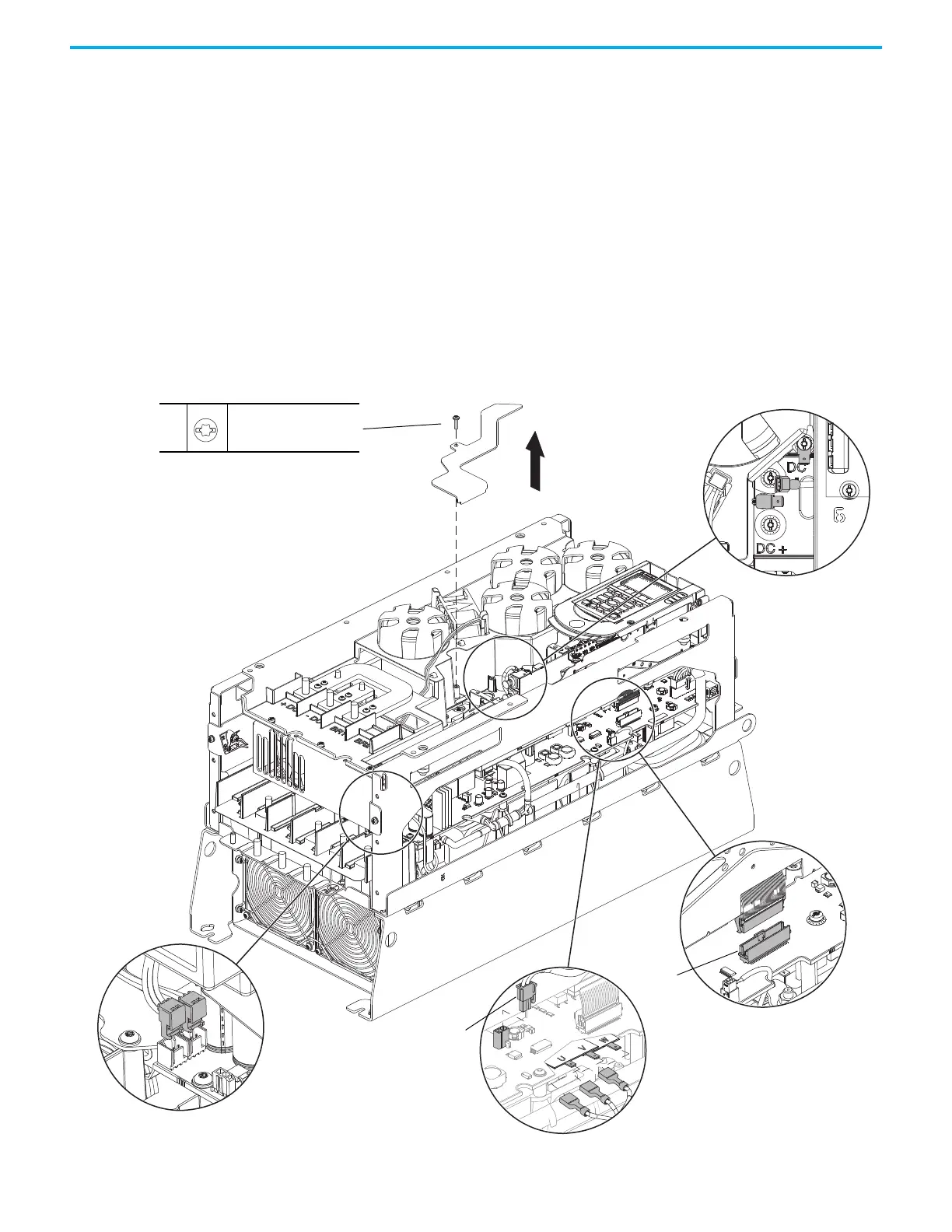
5. Remove the M4 x 12 mm Torx screw that secures the PE-B jumper cover
to the capacitor cover and remove the jumper cover.
6. Note the PE-B jumper position and if the PE-B jumper is in the OFF
position, remove the jumper wire from the connector on the power
interface circuit board.
7. Below the control pod, disconnect the ribbon cable connector from
connector J1 on the power interface circuit board.
8. If a torque accuracy module (TAM) is installed, complete steps a and b.
a. Disconnect the wire harness connector P4 from J4 on the power
interface circuit board.
b. Disconnect the wires from connectors U, V, and W on the power
interface circuit board.
9. Disconnect the lower stirring fan power wire-harness connector P5 from
J5 on the power interface circuit board.
10. Disconnect the upper stirring fan power wire-harness connector P6 from
J6 on the power interface circuit board.
5
M4 x 12 mm
T20
2.6 N
•m (23.0 lb•in)
6
7
9, 10
8
PE-B
J1
P4
U, V, W
P6 / P5

 Loading...


