164 Rockwell Automation Publication 750-TG101A-EN-P - June 2022
Chapter 6 Frame 7 Renewal Kits Installation
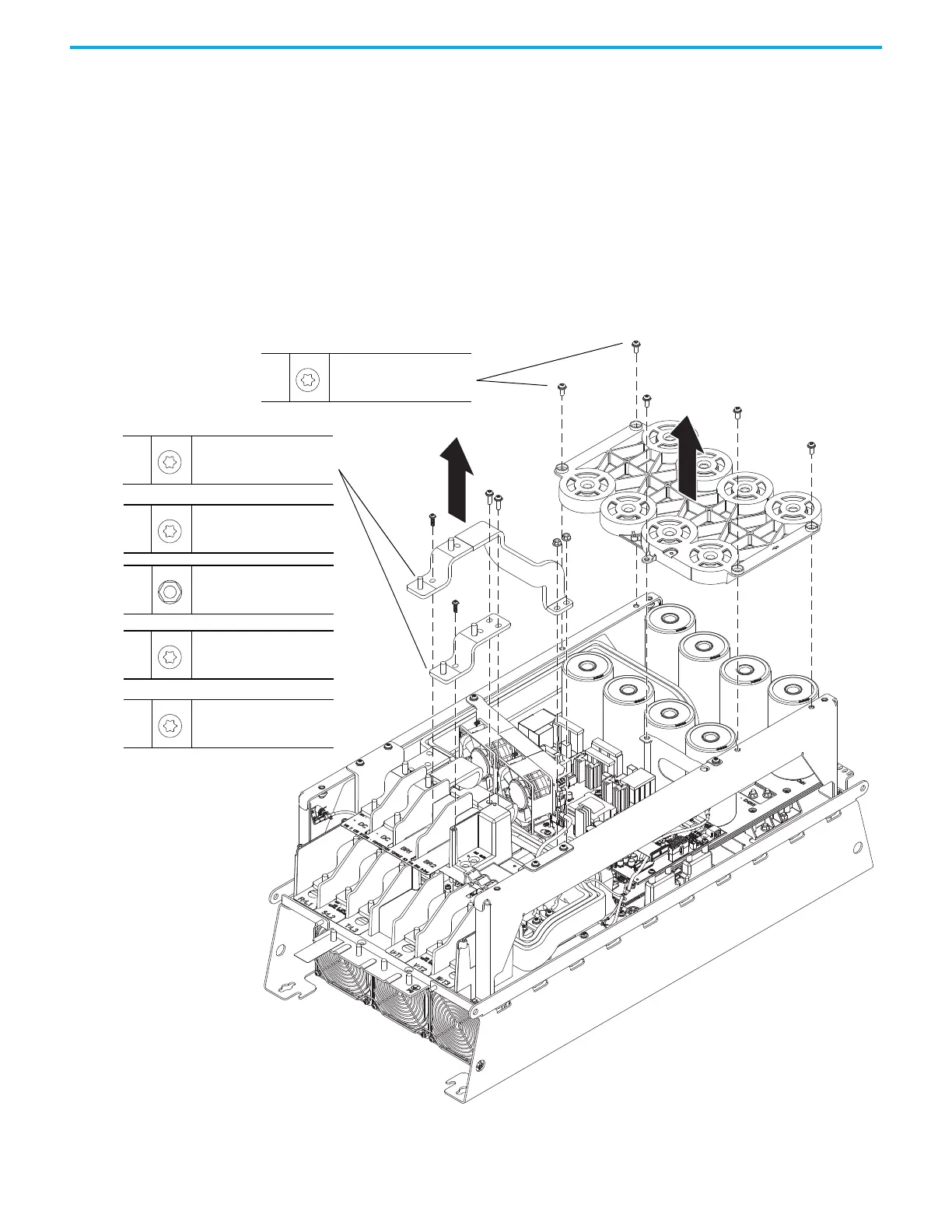
10. If the DC bus bars are installed, remove the five M6 x 16 mm Torx screws
that secure the capacitor bank cover to the chassis and remove the cover.
11. If a brake option is installed, complete these steps:
a. Remove the M8 nuts that secure the power cables to the brake
terminals.
b. Remove the M5 x 16 mm Torx screw that secures the long bus bar to the
BR1 terminal and remove the bus bar.
c. Remove the two M6 nuts that secure the long bus bar (BR1) to the lower
bus bars.
d. Remove the M5 x 16 mm Torx screw that secures the short bus bar to
the BR2 terminal.
e. Remove the two M6 x 20 Torx screws that secure the short bus bar to
the BR2 terminal and remove the bus bar.
10
M6 x 16 mm
T30
5.2 N
•m (46.0 lb•in)
11c
11b
11e
11d
11b
M5 x 16 mm
T25
4.9 N
•m (43.0 lb•in)
11d
M5 x 16 mm
T25
4.9 N
•m (43.0 lb•in)
11e
M6 x 20 mm
T30
5.2 N
•m (46.0 lb•in)
11c
M6
10 mm
5.2 N
•m (46.0 lb•in)
11a
M8
13 mm
11.3 N
•m (100.0 lb•in)

 Loading...


