174 Rockwell Automation Publication 750-TG101A-EN-P - June 2022
Chapter 6 Frame 7 Renewal Kits Installation
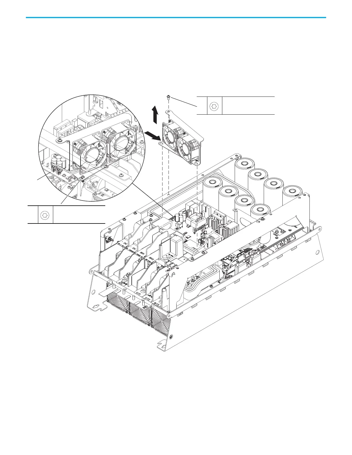
12. Loosen the two lower M5 Torx screws that secure the lower stirring fan
assembly to the chassis.
13. Remove the upper M6 x 16 mm Torx screw that secures the upper fan
assembly to the chassis side bracket.
14. Slide the fan assembly to the right, lift the fan assembly off the screws,
and remove the assembly.
15. Disconnect the fan-assembly power wire harness connectors P5 and P6
from connectors J5 and J6, respectively, on the power interface circuit
board (left side of the fan assembly).
13
M6 x 16 mm
T30
5.2 N
•m (46.0 lb•in)
12
M5 (2x)
T30
4.9 N
•m (43.0 lb•in)
P5 and P6
14
15

 Loading...


