Rockwell Automation Publication 750-TG101A-EN-P - June 2022 55
Chapter 4 Frames 1…5 Renewal Kits Installation
3. Remove the cover:
• For IP20, NEMA/UL Open Type, IP20, NEMA/UL Type 1, and flange,
NEMA/UL Type 4X/12 back enclosures, remove the power terminal
cover. See Remove the Power Terminal Cover, Frames 1…5
on page 35.
• For IP54, NEMA/UL Type 12 enclosures remove the cover. See Remove
the IP54, NEMA/UL Type 12 Cover, Frames 2…5 on page 37.
4. For IP20, NEMA/UL Open Type, IP20, NEMA/UL Type 1, and flange,
NEMA/UL Type 4X/12 back enclosures, remove the chassis from the
drive. See Remove the Chassis, Frames 2…5
on page 46.
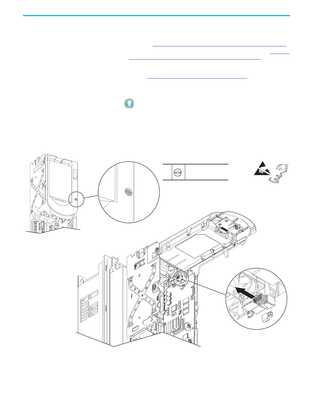
5. If used, disconnect the HIM DPI cable from the connector (port 2) on the
HIM cradle.
6. Loosen the screw that secures the HIM cradle to the pod chassis, and
rotate the cradle up to a 90° horizontal position.
7. If an option module is installed next to the main control circuit board,
remove the option module (not shown in this image).
8. Disconnect the fan power wire-harness three-pin connector from the
connector on the main control circuit board.
If a cable is not connected to the DPI port on the HIM cradle, be sure to leave the
protective cover installed.
Control Pod Shown Removed from the Drive Chassis for Clarity Only.
IP20, NEMA/UL Open Type Frame 2 Drive Shown.
Drive Chassis Shown Remove for Clarity Only.
8
6
M3 x 6.4 mm
T15 or F - 5 mm (0.19 in.)
0.45 N•m (4.0 lb•in)
 Loading...


