Rockwell Automation Publication 750-TG101A-EN-P - June 2022 65
Chapter 4 Frames 1…5 Renewal Kits Installation
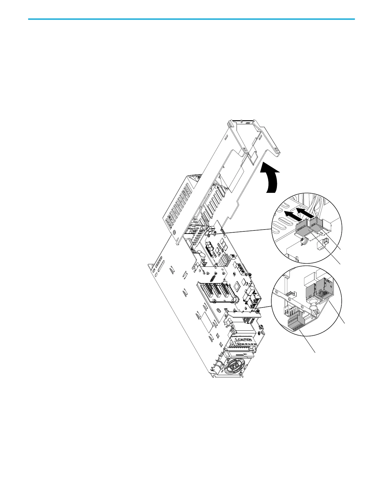
7. Rotate the chassis 90°, until the chassis locks in place.
8. Disconnect the jumper J16 from P16 on the main control circuit board.
Retain the jumper for reuse with the new main control board.
9. Disconnect the terminal block for the HIM DPI wire harness from the
connector on the main control circuit board.
10. Disconnect any cables from the Ethernet connectors on the bottom of the
main control board in the control pod.
11. If used, disconnect the plug-in terminal block (TB1) on the bottom of the
main control board.
12. If an option module is installed, disconnect any I/O wiring terminal
blocks and remove the option module (not shown in this image).
10
IP20, NEMA/UL Open Type
Frame 1 Drive Shown
7
11
9
8
 Loading...


