70 Rockwell Automation Publication 750-TG101A-EN-P - June 2022
Chapter 4 Frames 1…5 Renewal Kits Installation
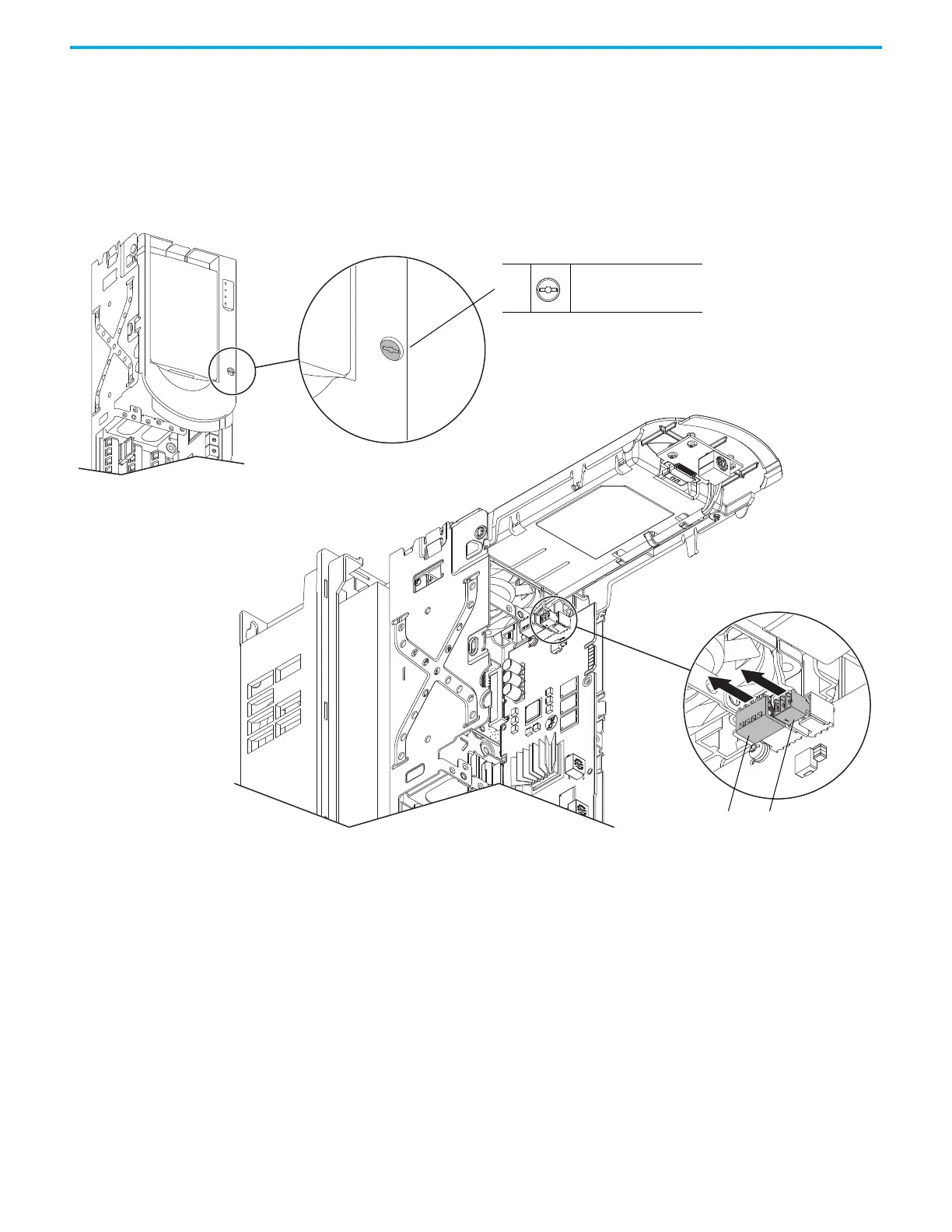
8. Loosen the screw that secures the HIM cradle to the pod chassis, and
rotate the cradle up to a 90° horizontal position.
9. Disconnect the fan power wire-harness or jumper (frames 4 and 5, IP54,
NEMA/UL Type 12 drives only) J16 connector from the connector P16 on
the main control circuit board. Retain the jumper for reuse with the new
main control board.
10. Disconnect the HIM wire harness connector from the connector on the
main control board.
Control Pod Shown Removed from the Drive Chassis for Clarity Only.
IP20, NEMA/UL Open Type Frame 2 Drive Shown.
Drive Chassis Shown Remove for Clarity Only.
9
8
M3 x 6.4 mm
T15 or F - 5 mm (0.19 in.)
0.45 N•m (4.0 lb•in)
10

 Loading...


