Rockwell Automation Publication 750-TG101A-EN-P - June 2022 87
Chapter 5 Frame 6 Renewal Kits Installation
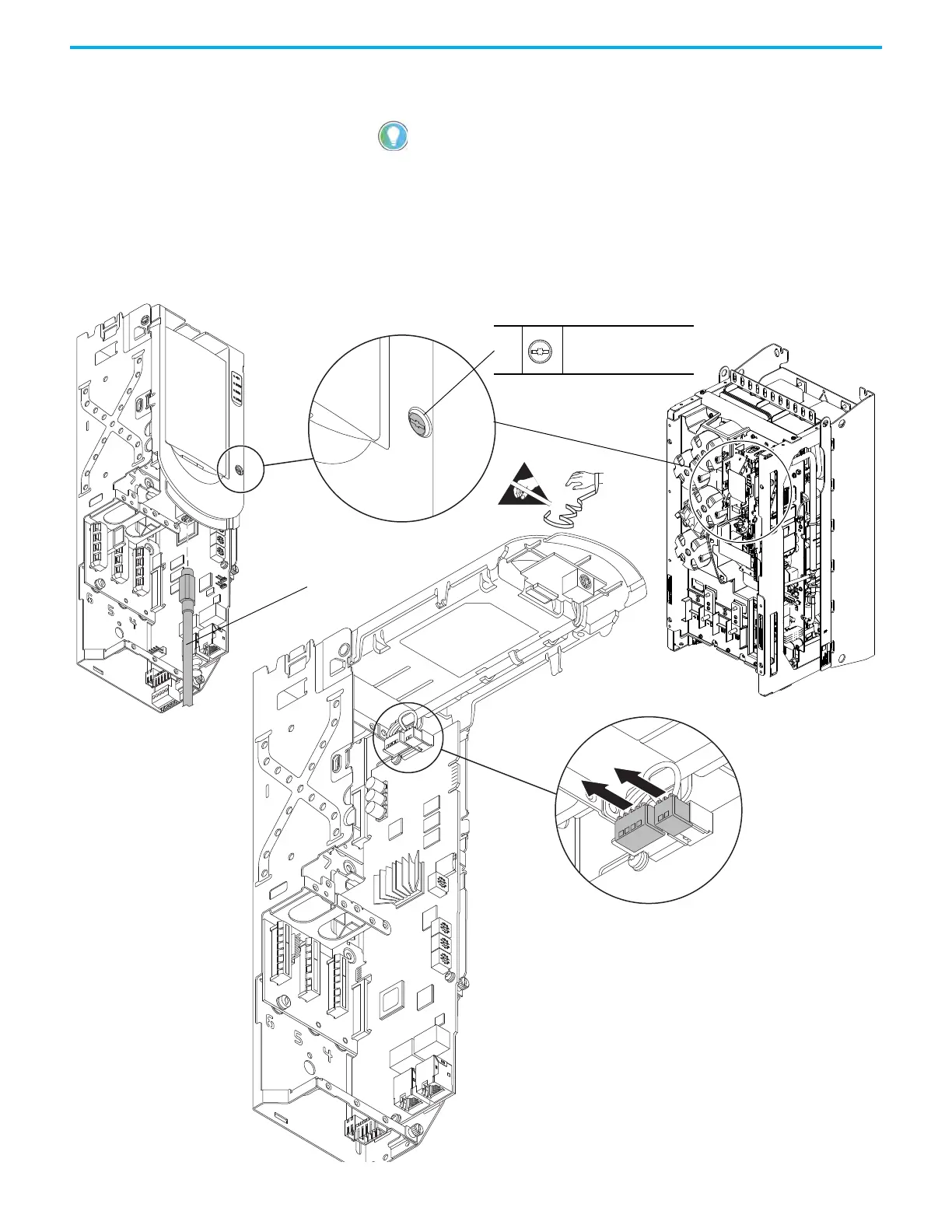
5. If used, disconnect the DPI™ cable from the connector on the bottom of
the HIM cradle.
6. Loosen the screw that secures the HIM cradle to the pod chassis, and
rotate the cradle up to a 90° horizontal position.
7. Disconnect the jumper J16 connector from the connector P16 on the main
control circuit board. Retain the jumper for reuse with the new main
control board.
8. Disconnect the HIM wire harness connector from the connector on the
main control board.
If a cable is not connected to the DPI port on the HIM cradle, be sure to leave the
protective cover installed.
7
Control Pod Shown Removed from the Drive Chassis for Clarity Only.
6
M3 x 6.4 mm
T15 or F - 5 mm (0.19 in.)
0.45 N•m (4.0 lb•in)
5

 Loading...


