Rockwell Automation Publication 750-TG101A-EN-P - June 2022 91
Chapter 5 Frame 6 Renewal Kits Installation
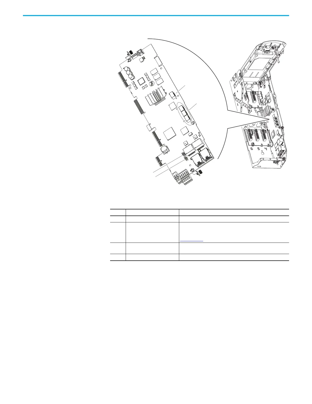
11. Record any application-specific settings on these main control board
switches or jumpers (identified in this illustration):
Main Control Circuit Board Details
Item Name Description
1 Control switch Rotary switch for setting the programming mode.
2 EtherNet/IP™ address switches
Rotary switches for setting the lowest octet of an EtherNet/IP address
(forces address to 192.168.1.xxx). See the PowerFlex Drives with
TotalFORCE Control Built-in EtherNet/IP Adapter User Manual, publication
750COM-UM009
for instructions on setting the IP address.
3 ENABLE jumper
Hardware enable jumper (P7). TB1 becomes an Enable when this jumper
is removed.
4 SAFETY jumper Safety enable jumper (P8). Removed when safety option is installed.

 Loading...


