PowerFlex Digital DC Drive User Manual - Publication 20P-UM001C-EN-P - July 2008
E-4 Installing a Communication Adapter
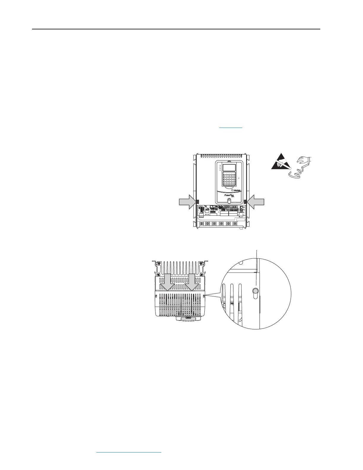
4. Remove the top cover from the drive:
a. For frame A drives, press in on the sides at the bottom edge of the top
cover and at the same time pull the cover toward you to pull it
partially off the drive chassis. Next, at the top of the drive, pull the
cover forward, away from the drive, until the pins fit in the keyhole in
the top of the cover, then carefully lift the cover off of the drive
chassis.
Important:The HIM assembly is connected via a cable to the Control
board and therefore will not pull free from the drive until
disconnected. See page E-6
for instructions.
=
Frame A
When metal pin fits in keyhole,
lift cover off drive chassis.
STS
PORT
MOD
NET A
NET B
 Loading...


