3-14 Wiring
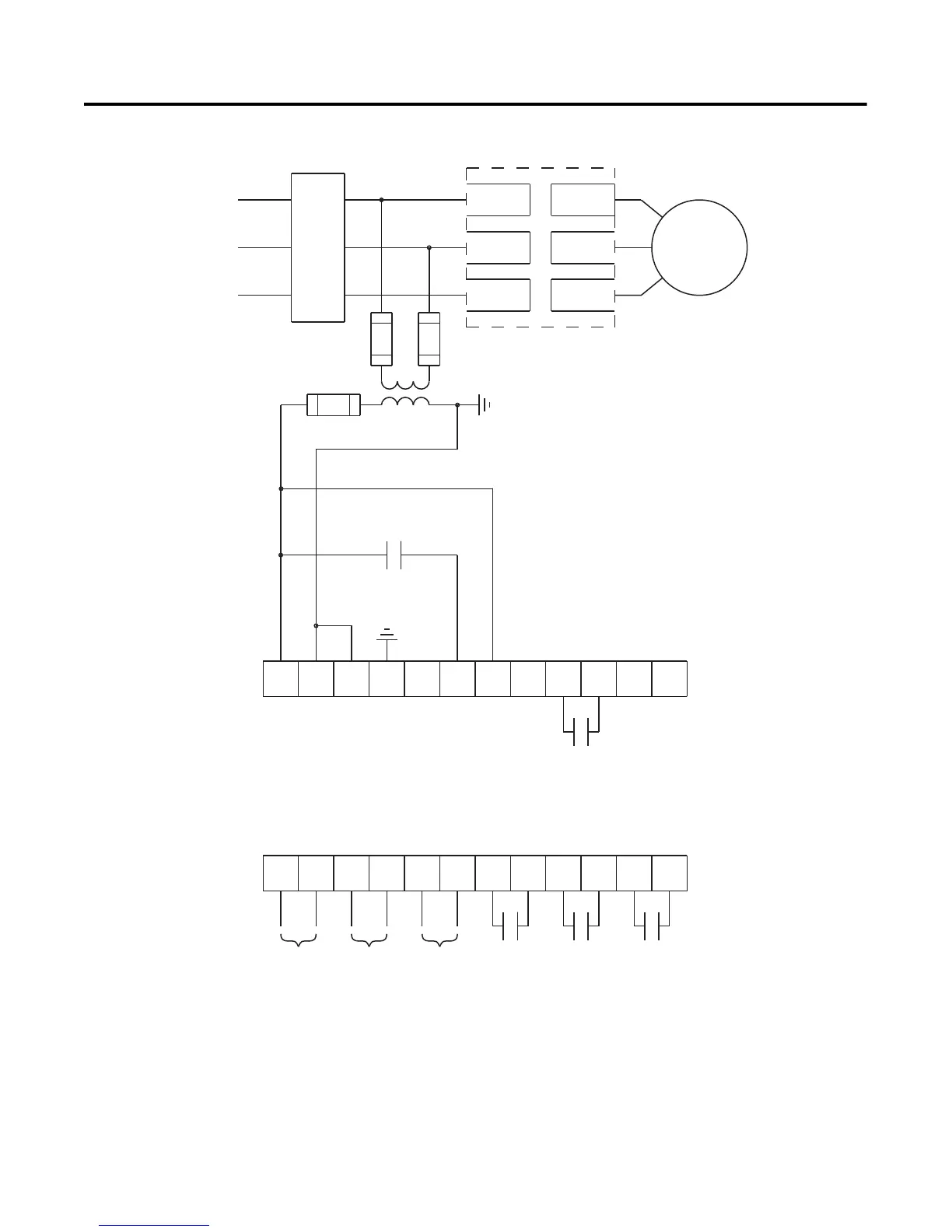
Figure 3.12 Typical Wiring Diagram for Two-Wire Control with Stopping
Control (No DPI Control)
➀
Customer supplied.
➁ Refer to the controller nameplate to verify the rating of the control power input voltage.
For units rated 625…1250 A, terminals 11 & 12 are factory pre-wired from terminal block
CP1 - terminals 1 & 4.
Notes: (1) Programmable controller interfacing in this diagram refers to hard-wiring between the
PLC’s output contacts and the SMC-Flex controller’s control terminals.
(2) The OFF state leakage current for a solid-state device must be less than 6 mA.
11 12
13
14
15 16
17
18 19 20
21
23
24
25 26
27
28 29
30 31 32 33
22
34
Two-Wire
Device
L2/3
L3/5
Branch
Protection
Input Power
3-Phase
SMC-Flex
Controller
T1/2L1/1
T2/4
T3/6
M
Aux #3Aux #2
Aux #4
Aux #1
SMC-Flex
Control Terminals
PTC
Input
TACH
Input
Ground
Fault
➀
➀
➀
➀
➀
➀
➁

 Loading...


