Wiring 3-17
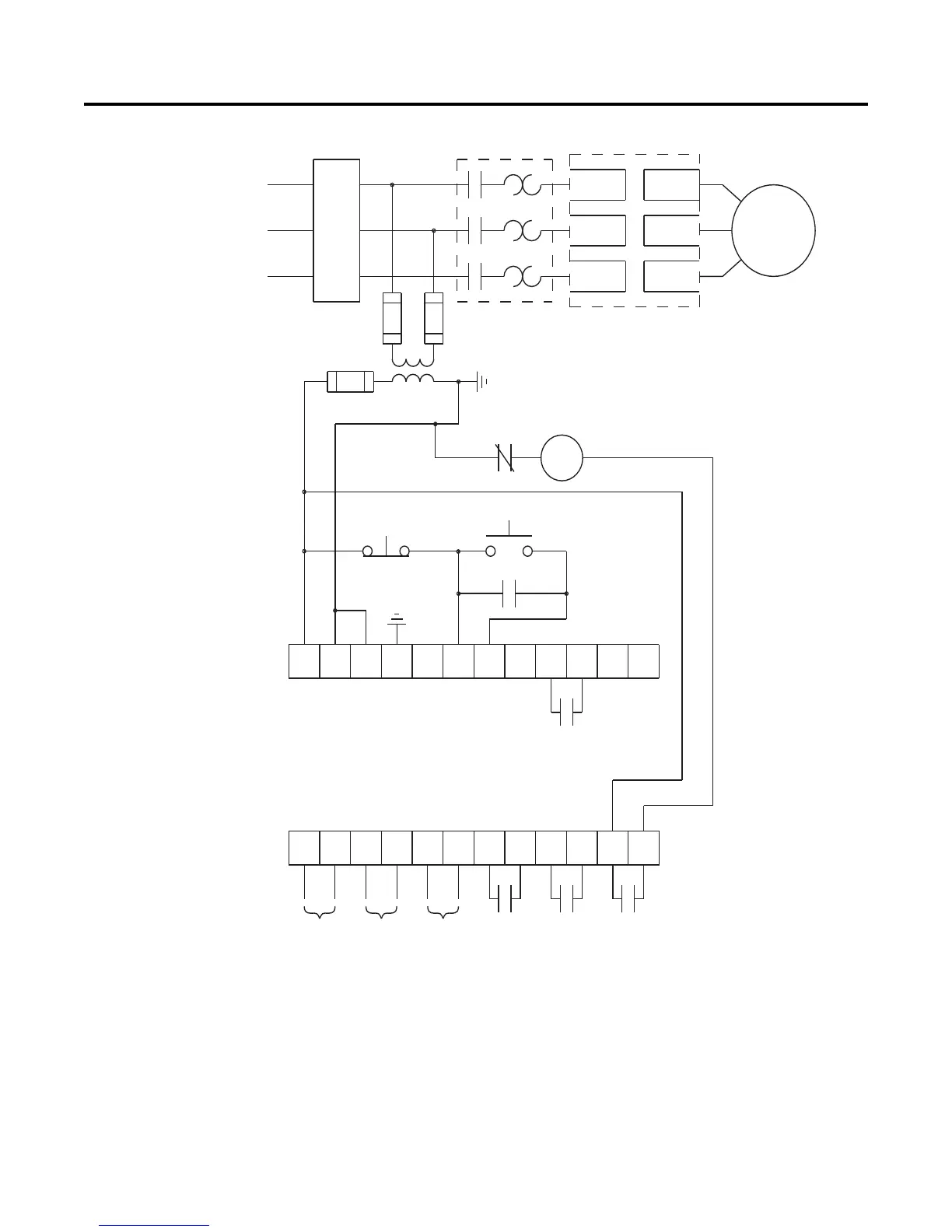
Figure 3.15 Typical Wiring Diagram for Retrofit Applications
➀
Customer supplied.
➁ Overload protection should be disabled in the SMC-Flex controller.
➂ Refer to the controller nameplate to verify the rating of the control power input voltage.
For units rated 625…1250 A, terminals 11 & 12 are factory pre-wired from terminal block
CP1 - terminals 1 & 4.
➃ Aux #4 should be set for normal operation
11 12
13
14
15 16
17
18 19 20
21
23
24
25 26
27
28 29
30 31 32 33
22
34
Start
M
OL
Aux #3Aux #2
Aux #4
Aux #1
SMC-Flex
Control Terminals
Stop
M
Branch
Protection
L2/3
L3/5
Input Power
3-Phase
SMC-Flex
Controller
T1/2L1/1
T2/4
T3/6
M
Existing Motor
Starter
PTC
Input
TACH
Input
Ground
Fault
➀
➀
➀➀
➀
➀
➀
➀
➀
➃
➂
➀➁
➀

 Loading...


