Note:
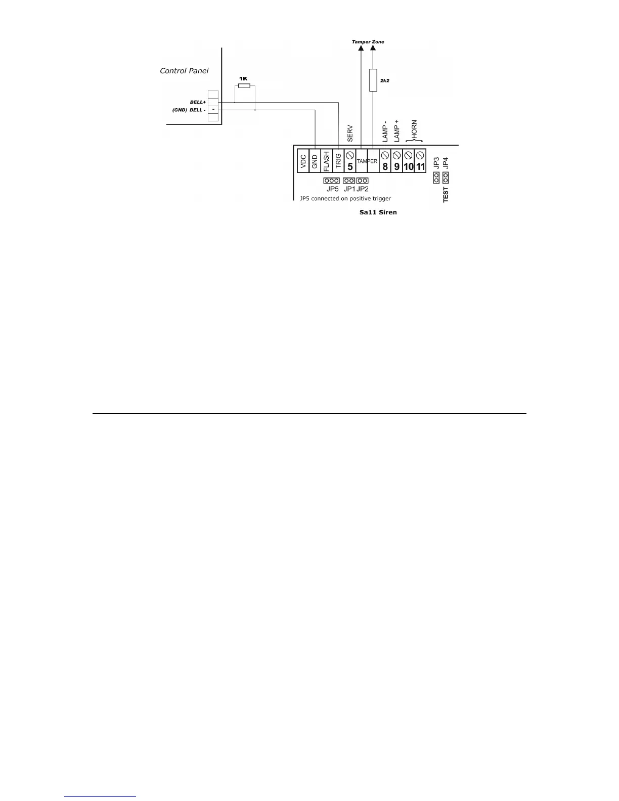
1. The picture above is an example of an outdoor siren connection (model SA 11) on CERBER C52/C82.
2. If both internal and external sirens are used simultaneously, the 2K2 resistor should be mounted in the
outdoor siren.
CERBER C52 : Z1, Z2, COM, Z3, COM, Z4, Z5
CERBER C82 : Z1, Z2, COM, Z3, COM, Z4, Z5, COM, Z6, Z7, COM, Z8
Terminals for burglary zones; see the general mounting diagram.
If any zones are not used, the corresponding terminals will be closed with 3K3 EOL resistors
on COM.
PHONE
Phone set connectors.
LINE
Phone line connectors.
COMMISSIONING
After completing all connections, reset the system by the following initializing procedure after
which the system will function normally.
RESET TO DEFAULT PROCEDURE
1. Disconnect power, both the battery and AC power.
2. Connect the reset jumper from the alarm system board.
3. Power Up the panel and wait for 2 seconds.
4. If the system has been reset to default, Zone LEDs will blink successively and the green
LED READY will be ON.
5. Disconnect power, both the battery and AC power.
6. Disconnect the reset jumper (take jumper OFF).
7. Power Up the panel. From now on, the system parameters are set to default values and the
system is disarmed.
Note: System initialization to default values may be done only if the “protection against undesired resets to default
values” parameter is disabled by programming. If system reset to default values cannot be accomplished, program the
respective parameter accordingly.
 Loading...