202208081959/V0.1
6 Electrical Connections
xMate ER7Hardware Installation Manual 29
12 DO_03
6.2.4.1 General-purpose DI
Digital inputs can be configured as PNP or NPN inputs. The user-input electrical
specifications supported in the two modes are listed below.
Min Typical Max Unit
Input voltage
range
21 24 27 V
The electrical principles in the two modes are shown below.
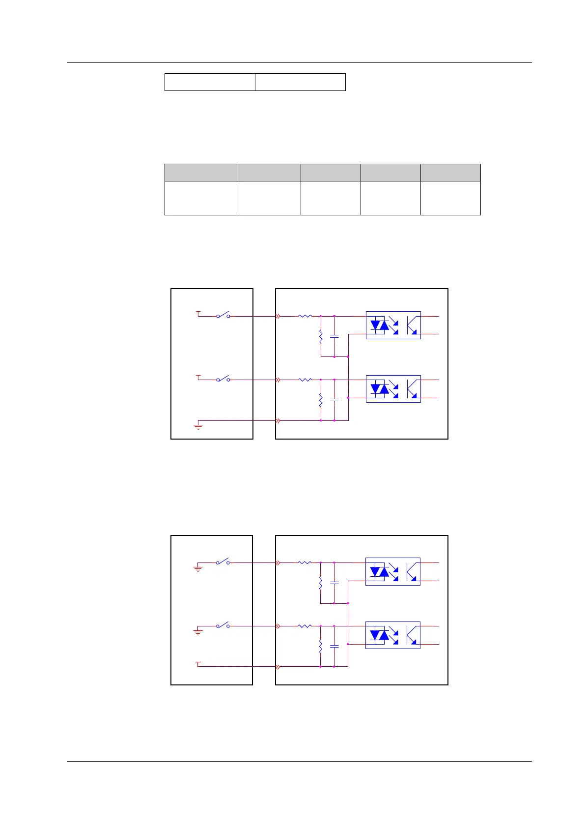
PNP input
See Figure 20 for details on a PNP configuration.
GND
.
.
.
.
.
..
.
DC24V
DC24V
DI_COM
DI_00
DI_03
1
2 3
4
1
2 3
4
Figure 20. PNP input wiring diagram
NPN input
See Figure 21 for details on an NPN configuration.
GND
.
.
.
.
.
..
.
GND
DC24V
DI_COM
DI_00
DI_03
1
2 3
4
1
2 3
4
⽤⼾端
机器⼈端
Figure 21. NPN input wiring diagram
 Loading...