202208081959/V0.1
6 Electrical Connections
xMate ER7Hardware Installation Manual 31
..
.
.
.
.
.
.
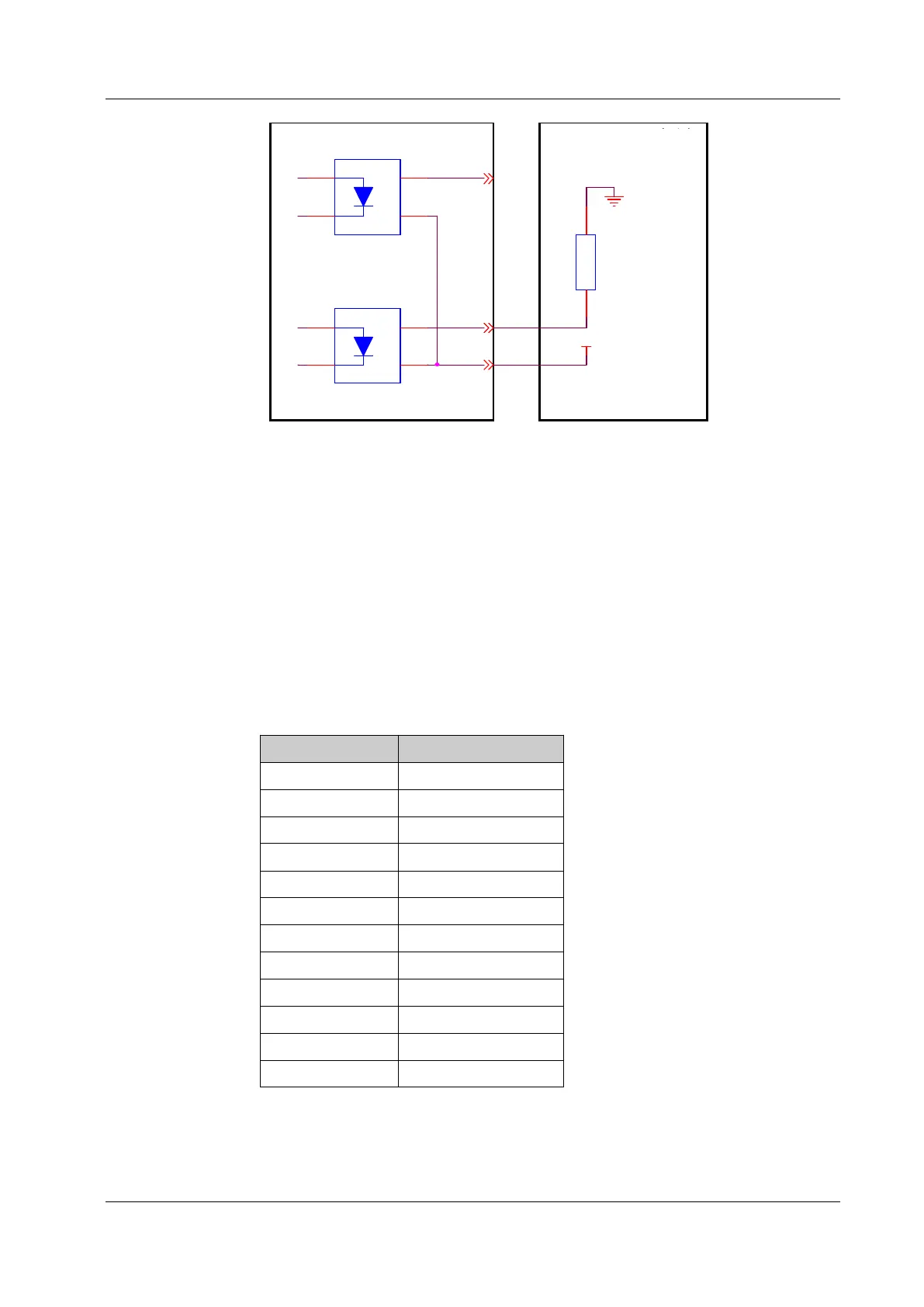
DC24V
DO_00
DO_03
DO_COM
V+
1
V-
2
D2
3
D1
4
LOAD
V+
1
V-
2
D2
3
D1
4
GND
Figure 23. PNP output wiring diagram
6.2.5 Safety DIO
xMate ER7 supports dedicated safety inputs such as external emergency stop and
safeguard stop (for example, the safety gate), and dedicated safety outputs such as safety
status feedback. The channels are located on terminal connector J7. Users must connect
to the corresponding channel using a cable with the E0308 pin-type cold-pressed terminal
in order to use this safety DIO function.
All safety DIOs are redundant in pairs and must be kept as two independent branches so
that a fault on one branch will not cause the failure of the safety function.
Point position Definition
1 VCC24
2 SGATE1
3 VCC24
4 SGATE2
5 VCC24
6 EXSTOP1
7 VCC24
8 EXSTOP2
9 STOP_STATE_00_A
10 STOP_STATE_00_B
11 STOP_STATE_01_A
12 STOP_STATE_01_B
6.2.5.1 Safety DI
The electrical principles and specifications of the safety DI interface are shown below.
 Loading...