6 Electrical Connections
202208081959/V0.1
30 xMate ER7Hardware Installation Manual
6.2.4.2 General-purpose DO
Digital outputs can be configured as PNP or NPN outputs. The user-output electrical
parameter specifications supported in the two modes are listed below.
Min Typical Max Unit
Load voltage
range
0 24 30 V
Continuous
load current
0
——
300 mA
If the continuous load current exceeds the limit, an additional relay will be required to
drive the system.
The electrical principles in the two modes are shown below.
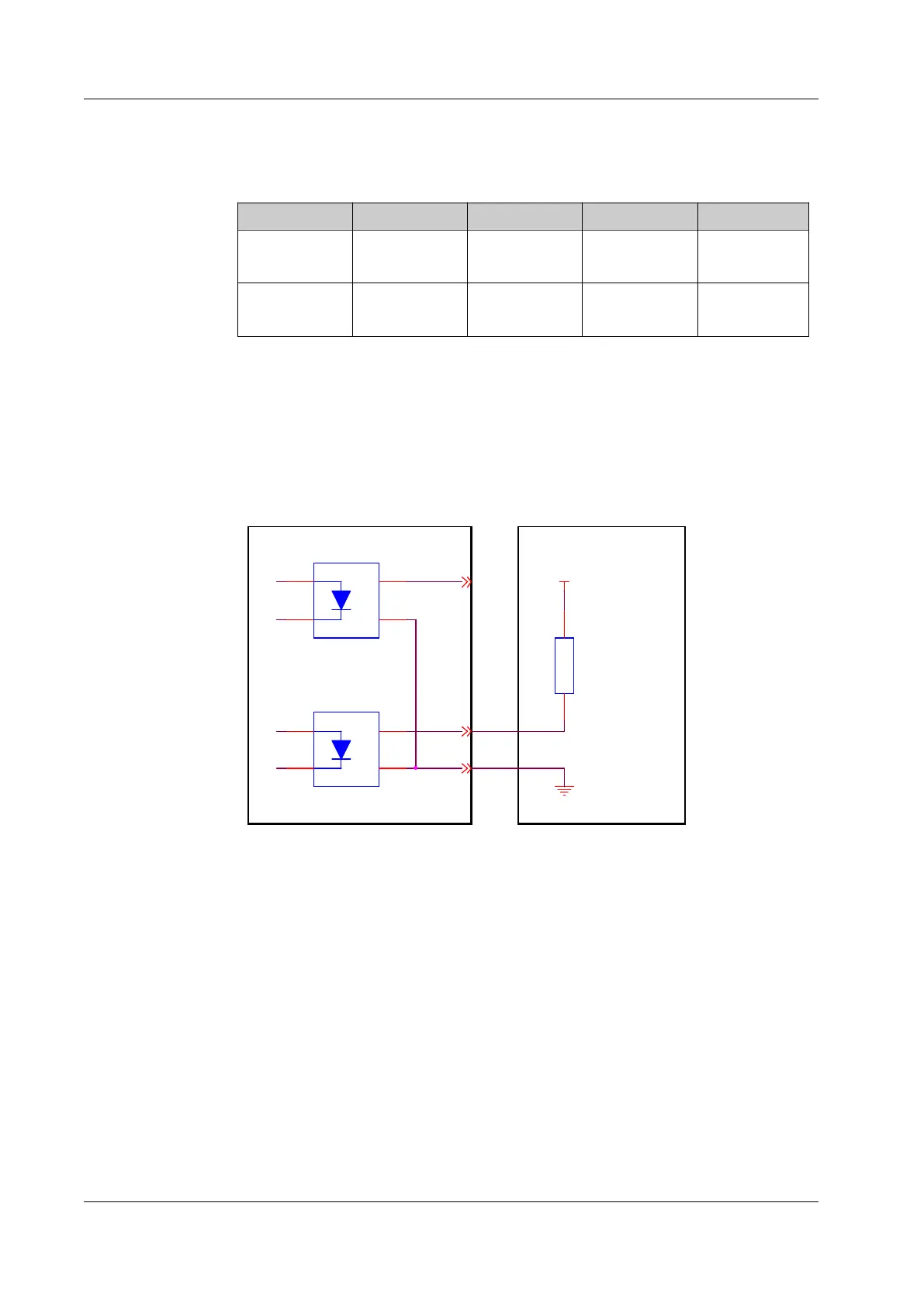
NPN output
Connect the DO_COM end to the negative terminal of the power supply, as shown in
Figure 22.
.
.
.
.
.
..
.
GND
DC24V
DO_00
DO_COM
DO_03
V +1
V-
2
D2
3
D1 4
V+
1
V-
2
D2
3
D1
4
LOAD
Figure 22. NPN output wiring diagram
PNP output
Connect the DO_COM end to the positive terminal of the power supply, as shown in
Figure 23.
 Loading...