57
Editing the system settings
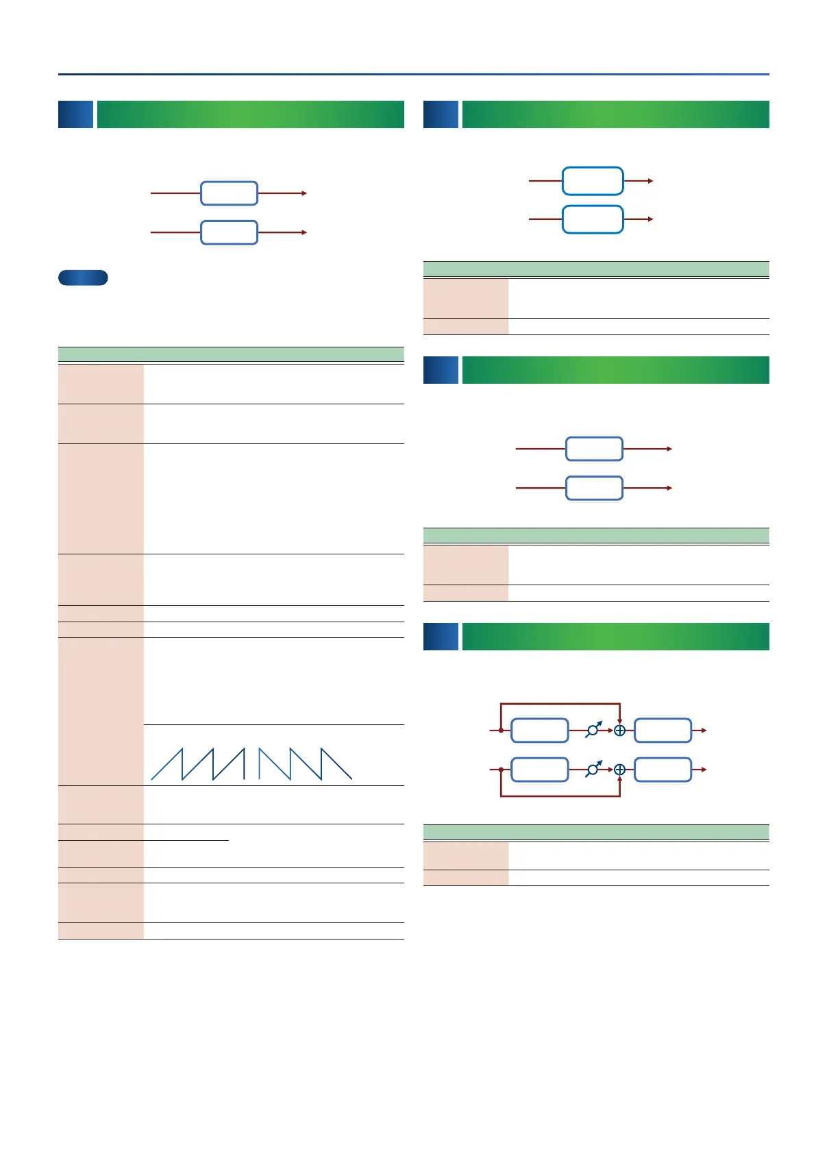
06 06 SuperFilterSuperFilter
This is a lter with an extremely sharp slope. The cuto frequency can
be varied cyclically.
L in L out
R outR in
Super Filter
Super Filter
MEMO
This eect can be used for both TOTAL FX and MFX. The parameters
than you can set when using the eect with the MFX are limited to
those marked with a (*1).
Parameter Value Explanation
Resonance
(*1)
0–100
Filter resonance level
Increasing this value will emphasize the
region near the cutoff frequency.
Cutoff
(*1)
0–127
Cutoff frequency of the filter
Increasing this value will raise the cutoff
frequency.
Type
LPF, BPF, HPF,
NOTCH
Filter type
Frequency range that will pass through
each filter
LPF: Frequencies below the cutoff
BPF: Frequencies in the region of the
cutoff
HPF: Frequencies above the cutoff
NOTCH: Frequencies other than the
region of the cutoff
Slope -12, -24, -36 [dB]
Amount of attenuation per octave
-12 dB: Gentle
-24 dB: Steep
-36 dB: Extremely steep
Filter Gain 0–+12 [dB] Amount of boost for the filter output
Modulation OFF, ON On/off switch for cyclic change
Modulation Wave
TRI, SQR, SIN,
SAW1, SAW2
How the cutoff frequency will be
modulated
TRI: Triangle wave
SQR: Square wave
SIN: Sine wave
SAW1: Sawtooth wave
(upward)
SAW2: Sawtooth wave (downward)
SAW1 SAW2
Sync OFF, ON
If this is ON, the rate synchronizes with
the tempo of the rhythm.
Ø “Changing the tempo (TEMPO)” (p. 36)
Rate
(Hz)
0.05–10.00 [Hz]
Frequency of modulation
Rate
(note)
Note
Ø “Note” (p. 75)
Depth 0–127 Depth of modulation
Attack 0–127
Speed at which the cutoff frequency will
change This is effective if Modulation
Wave is SQR, SAW1, or SAW2.
Level 0–127 Output Level
07 07 MM Filter MM Filter (Multi Mode Filter)(Multi Mode Filter)
This is a lter that is adjusted for eective use in a DJ performance.
L in
R in
L out
R out
Multimode
Filter
Multimode
Filter
Multimode
Filter
Multimode
Filter
Parameter Value Explanation
Filter Color 0–255
Filter resonance level
Higher values more strongly emphasize
the region of the operating frequency.
Filter Tone 0–255 Frequency at which the filter operates
08 08 Step FilterStep Filter
This is a lter whose cuto frequency can be modulated in steps. You
can specify the pattern by which the cuto frequency will change.
L in L out
R outR in
Step Filter
Step Filter
Parameter Value Explanation
Filter Resonance 0–127
Filter resonance level
Increasing this value will emphasize the
region near the cutoff frequency.
Rate
(Hz)
0.05–10.00 [Hz] Frequency of modulation
09 09 EnhancerEnhancer
Controls the overtone structure of the high frequencies, adding
sparkle and tightness to the sound.
L in L out
R outR in
Mix
Mix
Enhancer 2-Band EQ
2-Band EQEnhancer
Parameter Value Explanation
Mix 0–127
Level of the overtones generated by the
enhancer
Sens 0–127 Sensitivity of the enhancer
 Loading...