Reference Manual
00809-0100-4021, Rev FB
August 2011
A-13
Rosemount 3144P
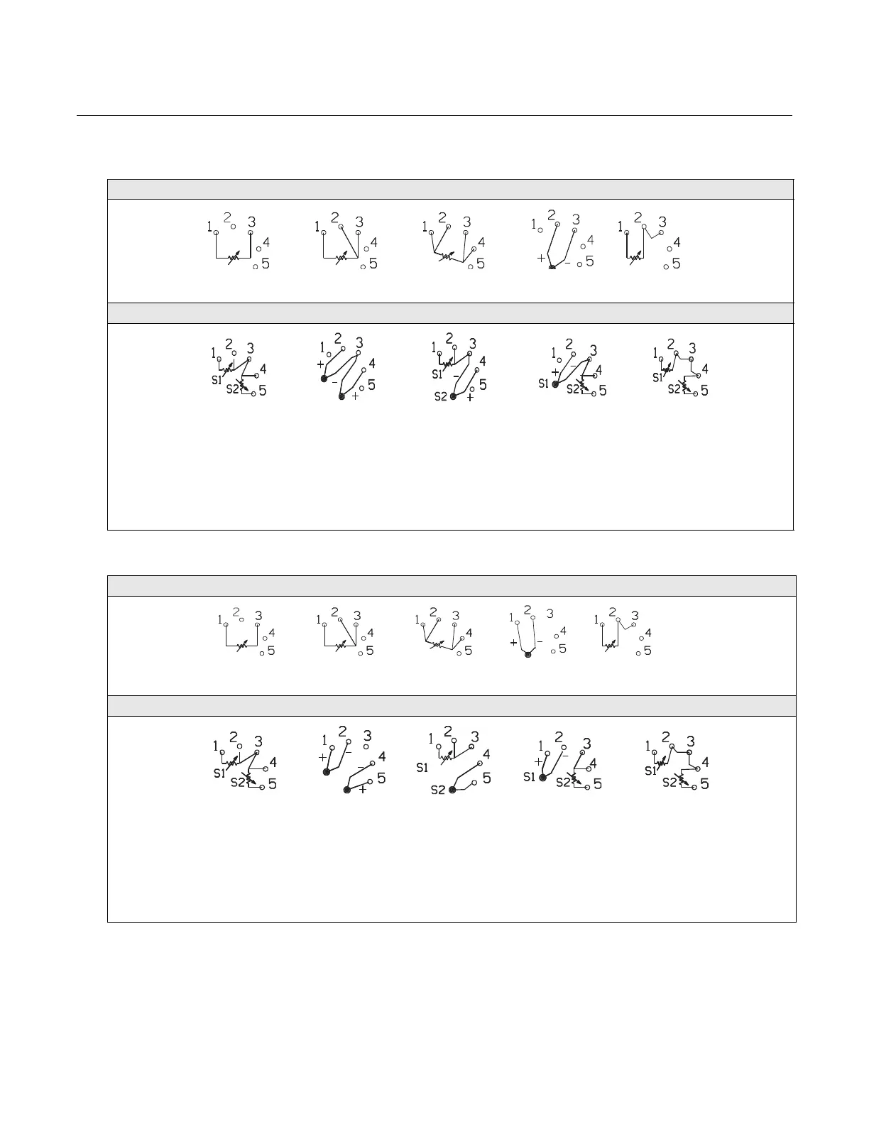
Figure 1. HART / 4–20 mA Wiring Diagram
3144P Single-Sensor Connections Diagram
3144P Dual-Sensor Connections Diagram
* Transmitter must be configured for a 3-wire RTD in order to recognize an RTD with a compensation loop.
** Emerson Process Management provides 4-wire sensors for all single-element RTDs. You can use these RTDs in 3-wire configurations by
leaving the unneeded leads disconnected and insulated with electrical tape.
4-wire RTD
and Ohms
T/Cs and
Millivolts
RTD with
Compensation Loop*
2-wire RTD
and Ohms
3-wire RTD
and Ohms**
T/Hot Backup/Dual
Sensor with
2 RTDs
T/Hot
Backup/Dual
Sensor with 2
Thermocouples
T/Hot
Backup/Dual
Sensor with RTDs/
Thermocouples
T/Hot
Backup/Dual
Sensor with
RTDs/
Thermocouples
T/Hot Backup/Dual
Sensor with 2 RTDs
with Compensation
Loop
** **
**
**
Figure 2. FOUNDATION fieldbus Wiring Diagram
3144P Single-Sensor Connections Diagram
3144P Dual-Sensor Connections Diagram
* Transmitter must be configured for a 3-wire RTD in order to recognize an RTD with a compensation loop.
** Emerson Process Management provides 4-wire sensors for all single-element RTDs. You can use these RTDs in 3-wire configurations by leaving
the unneeded leads disconnected and insulated with electrical tape.
4-wire RTD
and Ohms
T/Cs and
Millivolts
RTD with
Compensation Loop*
2-wire RTD
and Ohms
3-wire RTD
and Ohms**
T/Hot
Backup/Dual
Sensor with 2
RTDs
T/Hot Backup/Dual
Sensor with 2
Thermocouples
T/Hot
Backup/Dual
Sensor with RTDs/
Thermocouples
T/Hot
Backup/Dual
Sensor with RTDs/
Thermocouples
T/Hot Backup/Dual
Sensor with 2 RTDs
with Compensation
Loop
**
**
**
**