Reference Manual
00809-0100-4021, Rev FB
August 2011
Rosemount 3144P
4-14
FOUNDATION Fieldbus
ANALOG INPUT (AI)
Simulation Simulate replaces the channel value coming from the Sensor Transducer
Block. For testing purposes, there are two ways to manually drive the output
of the Analog Input Block to a desired value.
Manual Mode
To change only the OUT_VALUE and not the OUT_STATUS of the AI Block,
place the TARGET MODE of the block to MANUAL, then change the
OUT_VALUE to the desired value.
Simulate
1. If the SIMULATE switch is in the OFF position, move it to the ON
position. If the SIMULATE switch is already in the ON position, move
it to OFF and switch it back to the ON position.
NOTE
As a safety measure, the switch must be reset every time power is
interrupted to the device to enable SIMULATE. This prevents a device that
is tested on the bench from being installed in the process with SIMULATE
still active.
2. To change both the OUT_VALUE and OUT_STATUS of the AI Block,
set the TARGET MODE to AUTO.
3. Set SIMULATE_ENABLE_DISABLE to ‘Active.’
4. Enter the desired SIMULATE_VALUE to change the OUT_VALUE
and SIMULATE_STATUS_QUALITY to change the OUT_STATUS.
If errors occur when performing the above steps, make sure that the
SIMULATE jumper has been reset after powering the device.
Configure the AI block A minimum of four parameters are required to configure the AI Block. The
parameters are described below, with example configurations shown at the
end of this section.
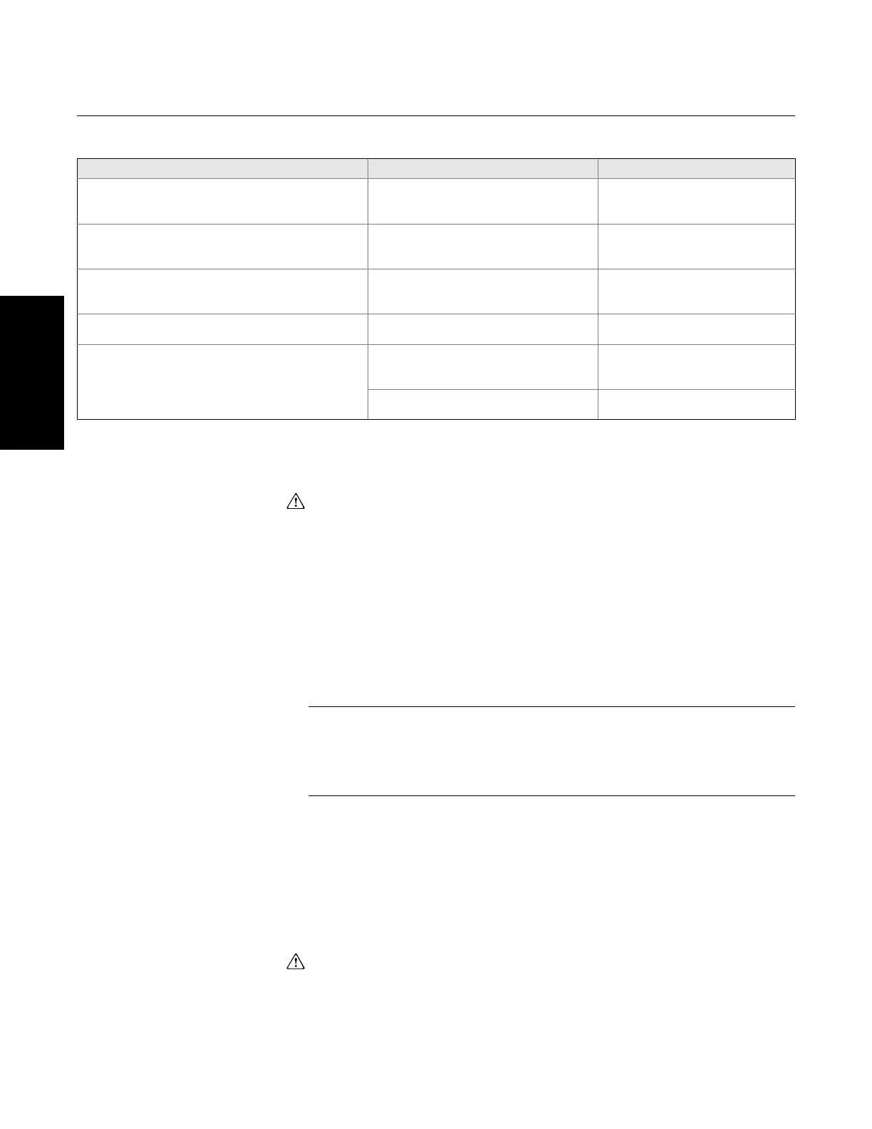
Symptom Possible Causes Recommended Action
The LCD displays “DSPLY#INVLID.” Read the
BLOCK_ERR and if it says “BLOCK
CONFIGURATION” perform the Recommended Action
One or more of the display parameters are
not configured properly
See “LCD Transducer Block” on
page 4-12.
The Bar Graph and the AI.OUT readings do not match The OUT_SCALE of the AI block is not
configured properly
See “Analog Input (AI)” on page 4-14
and “Field Communicator” on
page 3-14.
“3144P” is being displayed or not all of the values are
being displayed
The LCD block parameter
“DISPLAY_PARAMETER_SELECT” is not
properly configured
See “LCD Transducer Block” on
page 4-12.
The display reads OOS The resource and or the LCD Transducer
block are OOS
Verify that both blocks are in “AUTO”
The display is hard to read Some of the LCD segments may have
gone bad
See“Self Test Procedure for the
LCD” on page 4-13. If some of the
segment is bad, replace the LCD
Device is out of the temperature limit for the
LCD. (-20 to 85 °C)
Check ambient temperature of the
device