Reference Manual
00809-0100-4021, Rev FB
August 2011
Rosemount 3144P
2-12
NOTE
Do not connect the power/signal wiring to the test terminal. The voltage
present on the power/signal leads may burn out the reverse-polarity
protection diode built into the test terminal. If the test terminal’s reverse
polarity protection diode is burned out by the incorrect power/signal wiring, the
transmitter can still be operated by jumping the current from the test terminal
to the “–” terminal. See “Test Terminal (HART / 4–20 mA only)” on page 5-2
for use of the terminal.
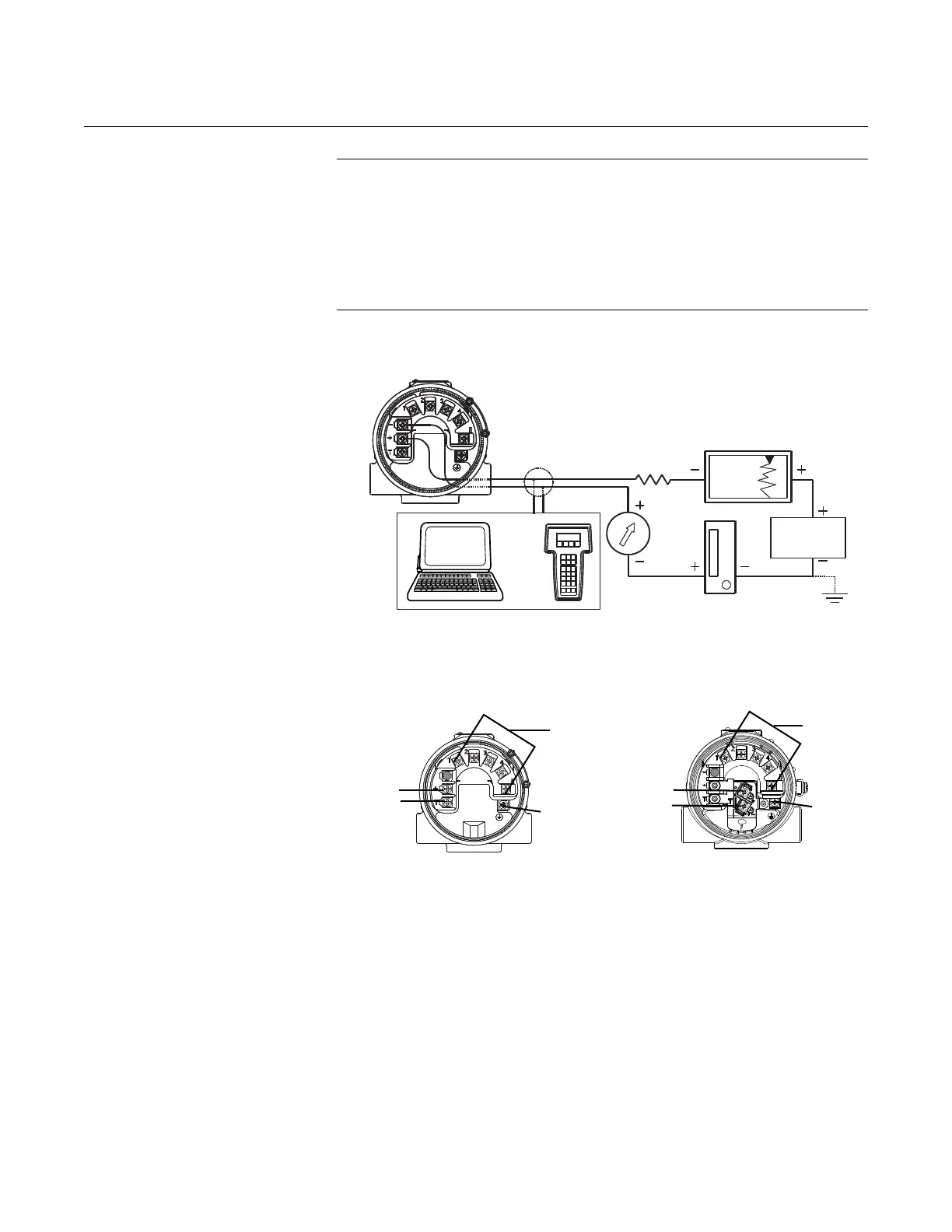
Figure 2-10. Connecting a Field
Communicator to a
Transmitter Loop (HART/ 4–20
mA).
FOUNDATION fieldbus
Figure 2-11. Transmitter
Terminal Block
Power/Signal Terminals
The signal wire may be grounded at
any point or left ungrounded.
Power
Supply
250 R
L
1100
AMS software or a Field Communicator can be connected at any termination
point in the signal loop. The signal loop must have between 250 and 1100 ohms
load for communications.
or*
Sensor
Terminals
(1 – 5)
Ground
Power
Terminals
Power
Terminals
Ground
Sensor
Terminals
(1 – 5)
WIRING CONNECTIONS
WIRING CONNECTIONS
(with “T1” integral transient protection option)