Reference Manual
00809-0100-4021, Rev FB
August 2011
2-11
Rosemount 3144P
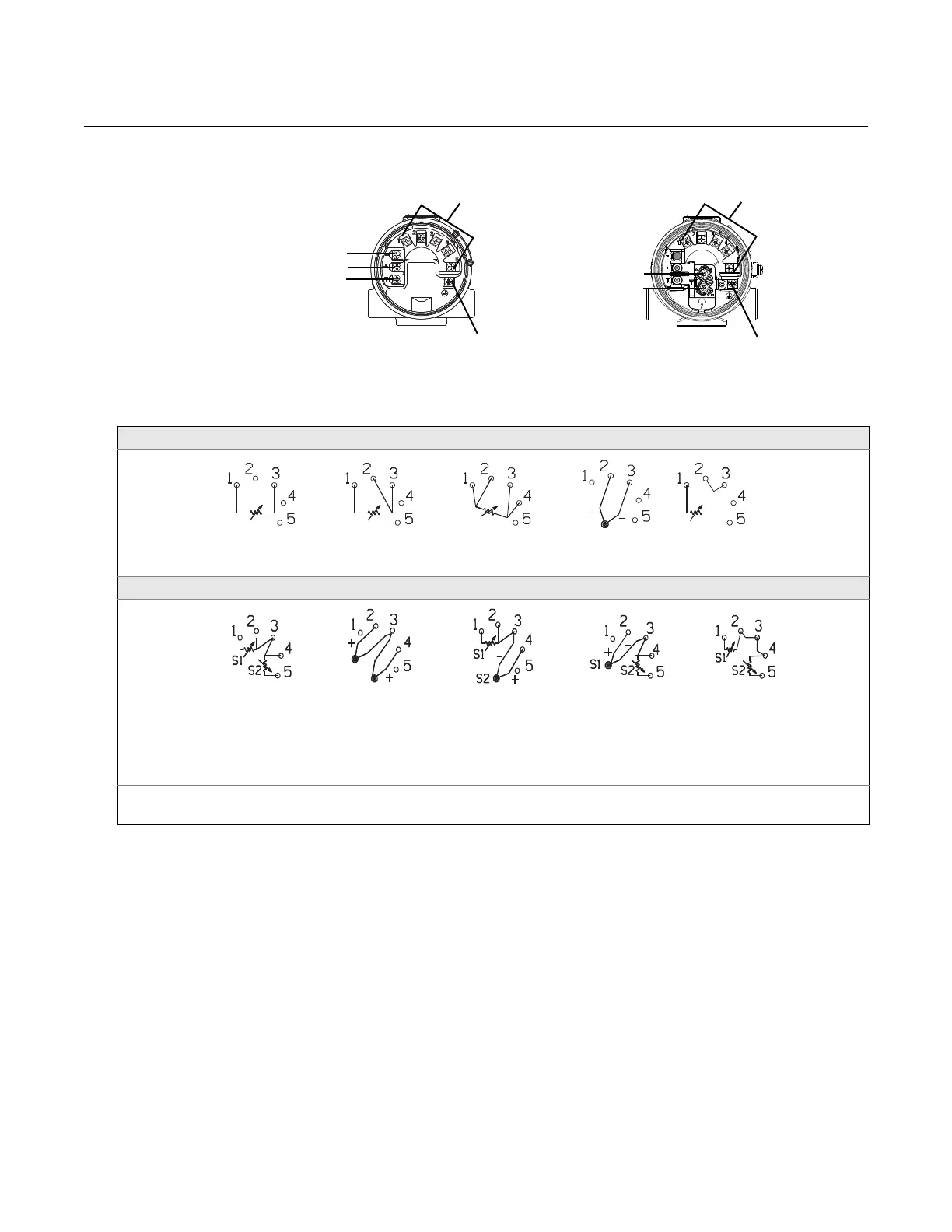
Figure 2-8. Transmitter Terminal
Block
Power/Current Loop Connections
Use copper wire of a sufficient size to ensure that the voltage across the
transmitter power terminals does not go below 12.0 Vdc.
1. Connect the current signal leads as shown in Figure 2-10.
2. Recheck the polarity and connections.
3. Turn the power ON.
For information about multichannel installations, refer to page 2-10.
Figure 2-9. Sensor Wiring Diagram for HART / 4–20 mA
3144P Single-Sensor Connections Diagram
3144P Dual-Sensor Connections Diagram
* Transmitter must be configured for a 3-wire RTD in order to recognize an RTD with a compensation loop.
** Emerson Process Management provides 4-wire sensors for all single-element RTDs. Use these RTDs in 2-wire or 3-wire configurations by
leaving the unneeded leads disconnected and insulated with electrical tape.
“+”
Sensor
Terminals (1 – 5)
Test
Ground
“-”
“+”
“-”
Ground
Sensor
Terminals (1 – 5)
WIRING CONNECTIONS
WIRING CONNECTIONS
(with “T1” integral transient protection option)
4-wire RTD
and Ohms
T/Cs and
Millivolts
RTD with
Compensation Loop*
2-wire RTD
and Ohms
3-wire RTD
and Ohms**
T/Hot Backup/Dual
Sensor with
2 RTDs
T/Hot
Backup/Dual
Sensor with 2
Thermocouples
T/Hot
Backup/Dual
Sensor with RTDs/
Thermocouples
T/Hot
Backup/Dual
Sensor with
RTDs/
Thermocouples
T/Hot Backup/Dual
Sensor with 2 RTDs
with Compensation
Loop
** **
**