00809-0100-
5-13
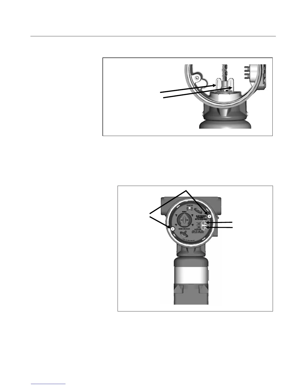
Figure 5-9 – Installation of
Electronics Assembly Connector
Plug
5. Push the electronics assembly (4) into the electronics housing (5)
and fasten with the two 6-32 captive screws. Torque each
captive screw to 7in-lbs ±1 in-lbs (0.8 N-m ±0.1 N-m), or hand-
Figure 5-10 – Installation of
Electronics Assembly
1. Install the terminal block assembly (6) into the “FIELD
TERMINALS” side of the electronics housing (5) and torque the
two 6-32 screws to 7in-lbs ± 1 in-lbs (0.8 N-m ±0.1 N-m), or hand-
are fully engaged under
lip of sensor module
potentiometers
and adjustment
screws are
aligned during
installation
Captive
Screws