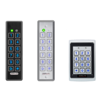
Reader Functionality
26 AYC-E/Q/T60 Family Installation and Programming Manual
5.2.4.2 Option 2: Single Key, Wiegand 6-Bit Nibble and
Parities
Each key press immediately sends 4 bits with 2 parity bits added –
even parity for the first 3 bits and odd parity for the last 3 bits.
0 = 0 0000 1 6 = 1 0110 0
1 = 0 0001 0 7 = 1 0111 1
2 = 0 0010 0 8 = 1 1000 1
3 = 0 0011 1 9 = 1 1001 0
4 = 1 0100 1 * = 1 1010 0 = "A" in Hexadecimal
5 = 1 0101 0 # = 1 1011 1 = "B" in Hexadecimal
5.2.4.3 Option 3: Single Key, Wiegand 8-Bit Nibbles
Complemented
This options inverts the most significant bits in the message leaving
the least 4 significant bits as BCD representation of the key. The host
system receives an 8-bit message.
0 = 11110000 6 = 10010110
1 = 11100001 7 = 10000111
2 = 11010010 8 = 01111000
3 = 11000011 9 = 01101001
4 = 10110100 * = 01011010 = "A" in Hexadecimal
5 = 10100101 # = 01001011 = "B" in Hexadecimal
5.2.4.4 Option 4: 4 Keys Binary + Facility Code, Wiegand 26-
Bit
This option buffers 4 keys and outputs keypad data with a 3-digit
Facility code like a standard 26-bit card output.
The Facility code is set in Programming Menu 4 and can be in the
range 000 to 255. The factory default setting for the Facility code is
000 (see Section 5.2.8 for more information).
The keypad PIN code is 4 digits in length and can range between
0000 and 9999. On the fourth key press of the 4-digit PIN code, the
data is sent across the Wiegand Data lines as binary data in the same
format as a 26-bit card.
 Loading...