EasyManuals Logo

Rotax 912 i series Installation Manual

Rotax 912 i series
206 pages
To Next Page IconTo Next Page
To Previous Page IconTo Previous Page
Page #35 background imageLoading...
Page #35 background image
d05165.fm
INSTALLATION MANUAL
BRP-Powertrain
Effectivity: 912 i Series
Edition 1/Rev. 0
10-10-00
Page 5
January 01/2012
All openings are protected against ingress of contamination and damp-
ness. It is recommended to leave the protective plugs in place until instal-
lation of the specific feed line.
NOTE: The transport equipment and plugs must be reattached if
the engine will be sent to the manufacturer or distributor.
Protective cover-
ings
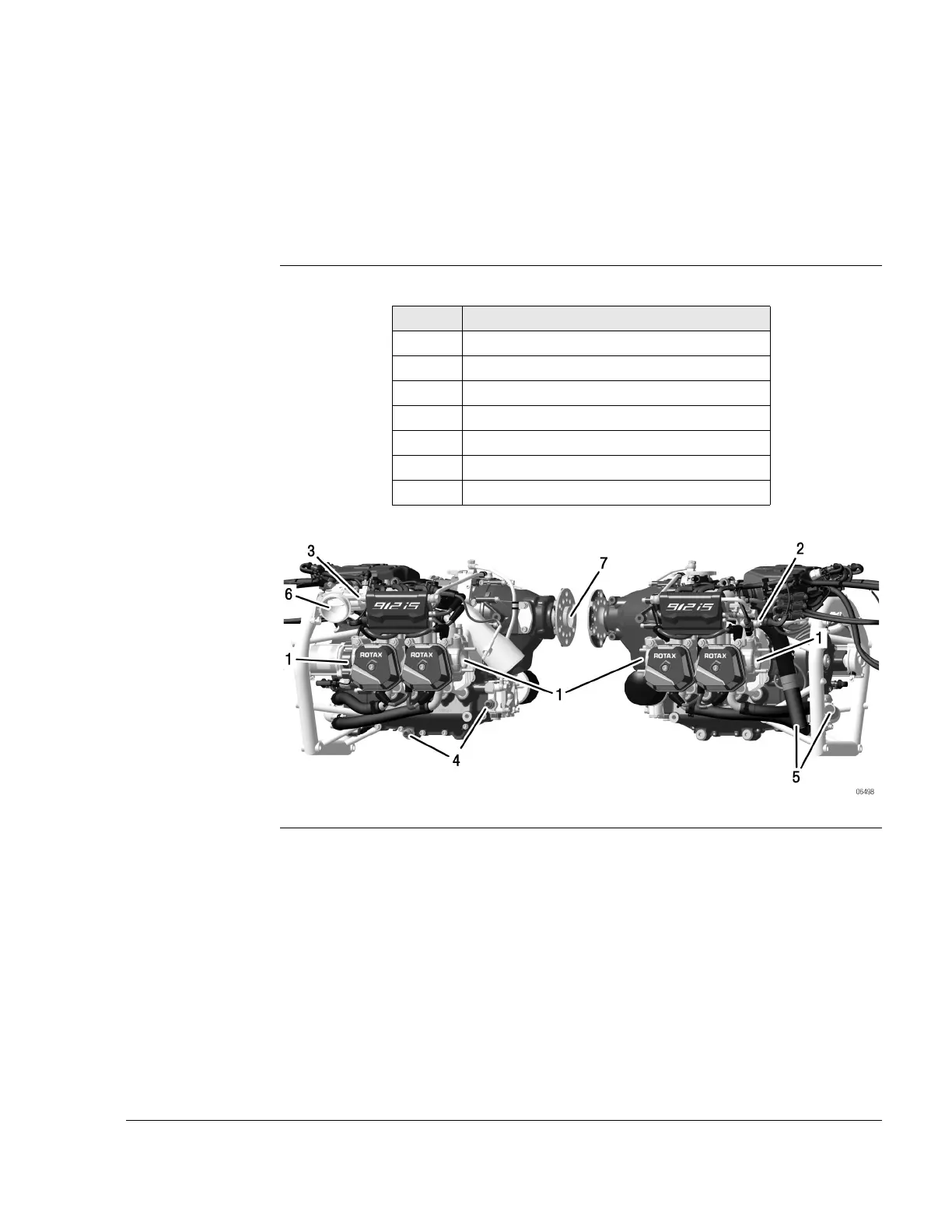
List of protective coverings. See Fig. 2.
Graphic
Fig. 2
Pos. Installation location
1 Exhaust sockets
2 Fuel rail (outlet) / fuel pressure regulator
3 Fuel rail (inlet)
4 Oil inlet/outlet
5 Supply and discharge of coolant
6 Throttle valve support assy.
7 Propeller shaft

Table of Contents

Other manuals for Rotax 912 i series

Questions and Answers:

Question and Answer IconNeed help?

Do you have a question about the Rotax 912 i series and is the answer not in the manual?

Rotax 912 i series Specifications

General IconGeneral
Number of Cylinders4
Max Power100 hp (73.5 kW)
Max Power Output RPM5800 rpm
Ignition SystemDual electronic ignition
Oil SystemDry sump, forced lubrication with separate oil tank
Reduction Gear Ratio2.43:1
TBO2000 hours
Engine Type4-stroke, horizontally opposed
Displacement1352 cm³
Bore x Stroke84 mm x 61 mm
Max Torque128 Nm
Fuel TypeAvgas 100LL or unleaded automotive gasoline
Fuel SystemElectronic fuel injection
Cooling SystemLiquid/air-cooled

Related product manuals