d05781.fm
INSTALLATION MANUAL
BRP-Powertrain
Effectivity: 912 i Series
Edition 1/Rev. 2
24-00-00
Page 27
January 01/2014
Performance of the key switch and operation of the relays.
NOTE: The interconnection with a display of the manufacturer
Stock Flight Systems
(www.stockflightsystems.com/www.rs-aerotech.com) was
shown. This functionality is not supported by all displays
on the market. The responsibility for proper selection and
installation of such displays is up to the aircraft manufac-
turer.
NOTE: The installation and specification of the Start Power Dis-
play depends on the pilot display output. The responsibility
of the specification and interconnection of the relay is up
to the display manufacturer.
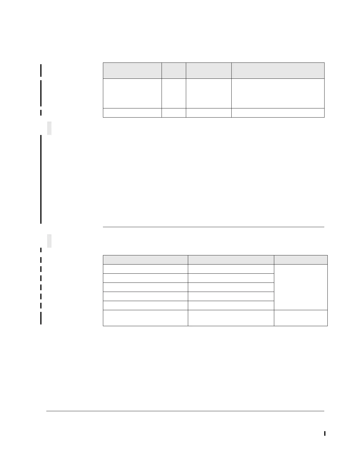
Specification of the additional components (additional to chapter 5.2)
Position of the key
switch
0 1 2
Start Power Relay Open Closed Closed (will open as soon as speed
> 1500 r.p.m.. Can only be opened
once. The correct sequence is con-
trolled by the pilot display)
Locking Yes Yes Spring return (to Pos. 1)
MASTER RELAY (optional) Requirement Connector/slot
Switch type Relay - continous duty
Nominal voltage 28 VDC
Nominal current Tbd from aircraft manufacturer
Min. control voltage Min. 6 V; Max. 18 V
Number of poles SPST NO (normally open)
Designation on wiring harness Not connected to the wiring har-
ness.

 Loading...


