pag. 22
ST2 User’s Manual
TV Mode
continuation: DIGITAL TV SIGNAL MEASUREMENTS: MEAS
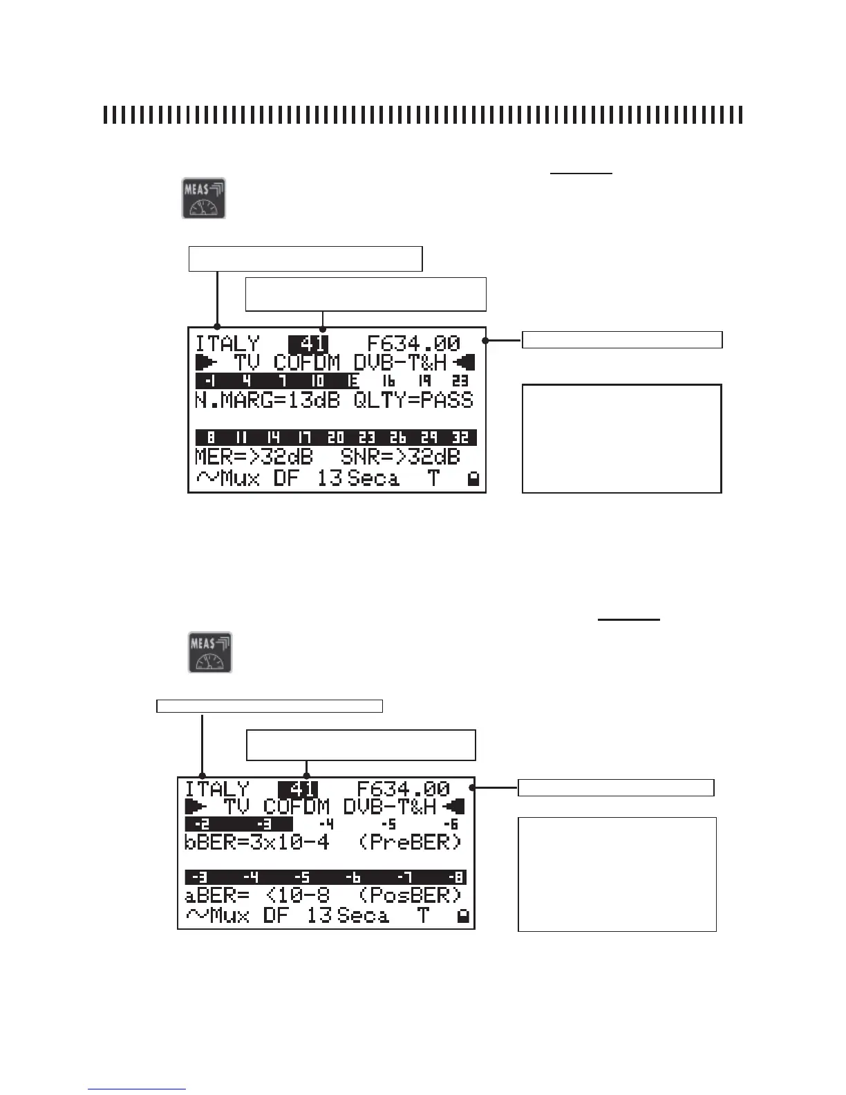
Fig. 4.2 The second level measurement provides the Noise Margin the MER (modulation error rate)
with their relevant graphic bars. Also the SNR measurement is shown as well as the quality analysis
(PASS, MARGINAL FAIL).
Press the
4.2 N. MARG, QLTY, MER and SNR measurements (Level 2)
key again to start the second level measurement:
Memory plan (See section 1.0)
Channel (See section 1.0)
NOTE
There are three variable fi elds
in this measurement level:
the Memory Plan, the channel
number and frequency. Only
on user generated plans.
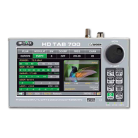
Fig. 4.3 the third measurement level provides the BER (Bit Error Rate) before and after the error
correction algorithms. The aBER (after Viterbi) shows the <10
-8
value for signals that can be con-
sidered error free after the correction algorithms.
Press the
4.3 BER measurement before and after error correction (Level 3)
key again to start the third level measurement:
Memory plan (See section 1.0)
Channel frequency
Channel (See section 1.0)
NOTE
There are three variable fi elds
in this measurement level:
the memory plan, the channel
number, and frequency. Only
on user generated plans.
Channel frequency